1963 CA95 Restoration

transmission and crank cases

now the shift forks have arrived I was able to finally reassemble the bottom end of the engine. I checked I could go through all the gears before joining the cases, as demonstrated in this slightly cack handed video:


as the mating surfaces of the crank case are interrupted by the bearings in the transmission Honda could not use a gasket between the upper and bottom cases and instead used a gasket sealant. Here is what I found out when researching gasket sealant:

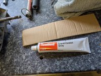
It seems you should not use a silicon based sealer: apparently it is too squishy and if any sealant squeezes out of the joint inside the case it can break free and block oil-ways in the engine. Instead the recommended product is Hondabond, which is firmer and sets to a sort of malleable but stiff consistency. As far as I can tell the same product is also branded 'yammabond' and ThreeBond. Threebond is available in the UK so I got that.

ACtC-3c24rIKcc53a2k2Md5hMfCz1QWSr0k7LsfH-ylylKSH0vnnvU9DQ9A-lrIAowm50PbtHccoIMY68VxyaYMZSmMuK9bju-DS1mY18-v7jjHYW4YyAW3xEYpu8laXw-8DFWRFoDXHQpgotwT3txWgarX3iw=w1910-h1432-no


I could not find out much consistent advice on how to apply it, and the only instruction in the CA95 manual is to 'apply a coat of gasket sealant on the mating surface'. I think coat must mean a 'thin coat' since the two mating surfaces are already machined flat and the sealant is only needs to fill any imperfections left by the machining process.

In the end I decided to follow what I saw on a random youtube video and dabbed it on with my finger. The sealant does seem to go off quite quickly: the Therebond instructions say to fit the parts 'within 1 minute' but I think I took rather longer than that!

ACtC-3fKQuBtjs9C6f7dxsWAm_H8hUsTVbY8o9faJ6J_zcuF2srSIc7vyaeJhcwbv9sD6G4FCWGz8uxRlRnxqrKc2CS4FKS9sWSAiE1PY89CMCeOEBk7TEZvFlsrSgJfQbH1U3XSuCIA7-5KE-vJVh-poMMo0A=w1074-h1432-no


As suggested elsewhere I did a test fit first and laid out the variously sized bolts by inserting them into a bit of card matching their location on the cases to speed up fitting.

There was very small amount of squeeze out all around the case so I can confirm that the finger dabbing approach - although perhaps not the text-book way of doing it - is at least idiot proof!

ACtC-3cqxJtgjXatIzDS89VcW9btjavpA7m9u36T2ppJFVnj4m7Fff0K70dKSZI4jkyfqbu32D7xZ5df8BxeUXCgmRmYvNgijpShTR8oCdG0zmQtXMF5hNZR7hwbxJ8ouY5m_2nrG8VRd4Gl7y4tvHjBuyVwJg=w1910-h1432-no
 

Attachments

  • IMG_20200606_141044.jpg
    IMG_20200606_141044.jpg
    232 KB · Views: 4
petcock refurb

It was said earlier on in this thread that these petcocks (fuel taps) need to be checked for leaks and it is not hard to see why. I have replaced various washers and seals with original Honda parts, so hopefully this will keep it fuel tight.

The old seal between the fuel bowl and the part that screws to the tank had a lip, but the new part is a simple flat washer (the old one had split along the seam so perhaps that was a weak point).

ACtC-3dn_7o_2zgvjjfpvhkPgTK8IRPfEN6PtaMSSooE1SQlG2y8pdGJ_iQrKRCSKJtDuWWP7Z0zqOWZl3YYzyq1pkxfwoBVYgXfdSJY1jU6eMUrvS3S0_y2DLxrMm_jB9T4PkMt_jS8psQNr4CSXZpwTs0ETw=w2040-h1530-no


the washers used for the screws holding the petcock seem to be made of a special material - I've seen these red washers referred to as 'phenolic' washers in electrical parts but I don't know if this imparts any special property relevant here (I suppose it is important they can cope with vibration?)

ACtC-3dwOs1D-GpxaKHztrPsREK9QA2Ap8DzqeBJgioummaR0ymEnuDQZk_kUIPCgi7P5qQ0mmjxH68aE1BlZFE_6bX7-NWGlHbLUS7wZa-1z2vFk9v0oQjem4tQFZ36RcsTmfq_xNKl8ox5JFNfwYb70kpGtg=w2040-h1530-no


finally there is a cork washer that fits under the lever. I suspect this is the most vulnerable part, at least given how compressed the old one is (as you can see is squashed to about half the depth of the new one):

ACtC-3emPhLUduv3n4VacoBpaiQnTj6yHpp-8Xtv-QO5KXCPfHjCT7S4V2Zs0xlPmNVzJ3wgY6z9HfZcVwUxOXoRxG4o8X6DPOTL00a8zlBdSELeDAfOf7SjKk7VwJ9cso13mtqXIp3iQ75iACH0KWjUZUFBuw=w2040-h1530-no


It is almost as if the people who specified this washer had not anticipated the same washer still being in place 60 years after it was put in!

Adding in the the fact that the lever is constantly moving back and forth over the cork washer to expose/close up the holes for the main and reserve tubes and that there is nothing really to stop dirt and water getting in between the cork washer and the lever and there are lots of opportunity for leaks.

ACtC-3dMu_HYnhMPNAimPcaU8axkNqmEdfrcbD78srgWCGhAA8IjgntGHphS5OeHZ_gFupBSVIt9xytTRg-rEN-vsgubCkpawjkyVNyFCVhbdojiVn_681Daikd_B0GStBOgdtkSjc3GUQGOQyPW7BnwdxTBkw=w1148-h1530-no


ACtC-3erEGf-KPP3aLGVYJRayxs79_zjSujvVnv4Dw0StdBZvZE42DhGwBU6aKkHuNhwMMQgZfeOsbrji1RvuOU1NeEcsbzKjYEgkHADTZ4EhXt5gL0Yf8nMFHkMeiA3CrXYL-iVvG6BvfQxfwNniZHyk1eKSg=w2040-h1530-no

does anyone recall how they faired in practice back in the day?


ACtC-3etwdjVr0o1fiQA2JIyKqmrmKArR9QLfVw6uFIXQgkA2TqO_3DAOfyeORd2tN6KRCLDBaFOXqjGIU_mWRMWUwgSSQplhNCMg5DrRf__0-2hmfLWwllwYQ_qzY-kgzpRDJeGMTDNTO_xtlIWQhEXXxdqHA=w2040-h1530-no
 
Other than the CA72 I had for maybe 6 months very early in my riding life, I've not had any experience with the older style petcocks like that one. I will say that at least it is made up of parts that can be replaced if you can find them. Looking back, I always thought the design was such that it allowed repairs while the later versions along the way were less likely to be rebuildable, and some not at all. The attention to detail you've given this project is tremendous, I'm enjoying watching the process.
 
Daft questions

cheers Tom!

I have a couple of questions that I should probably be able to work out myself (but can't):

I haven't been able to attach the kick starter spring: The long arm of the spring fits into to a hole in the upper case and it seems the idea is to tension the spring by twisting it anti-clockwise and then hooking it on the tab on the spindle, but I just can't figure out how to do it. Is there a special technique or do I just have to apply brute force?

ACtC-3dG9-O2J6ambZ5SvFIdne4Kml7VRrnKNBXvuZZDsoeRjDmQo7FXNGX6VemT1UpDwYn1axejvVC7RCLxO8_WFcPyhS1xdzYYhzALXThXz6S8FfQ9pDQXLicv82F4Smu2B1qCkpuP8eKlJ8vPsLX3x7-ieg=w747-h996-no


ACtC-3fsPBP0MWTeR_yqSV86-t5tPbZqKEmtOtSfgbXV6SbXudrKR5sP2UVutNj1dm_flmqYqYE_XJzZUf_2did5KmDO1qbF7aWEzWCy9PEr9yxg00FSZDSWwOcmzlsYWvnLEphbmYBcZtdpYwKmSy-x-Su8Xg=w747-h996-no


Q2: the upper and lower cases are cast with a deep recess in them and a hole that goes top to bottom - but why!?

ACtC-3fSamGuXJZamQonXsAfKzkYVgwH_FluYE1b4r39KvcSIS_gOUC9jpvqNIAlvG5hVVPxJfWrLJWV_-8Gg3Ge1scyqECHhuZZk8A2u0JhcAM99IcAwSzkJo0aiynk4fDYeyQpcGb_mgp7Mb-TqqsNlC-yPA=w537-h716-no


ACtC-3dG11r9k0gf9ZL0IqklT4n8S1uWO9cHoETmhbRown5xnef6poG4S6Y_NjVpIRxXUaauYC1e3tE8o_oWbyRsbZvlmfJRajzuxxiZuJajlKANJ9iCDsN-8E99dKVFOX0rKx43LOdMUN5LQwDWl4i3ngL9qQ=w597-h796-no
 
pistons and cylinder

it appears I got lucky with my guess that a 0.25mm rebore would be enough to remove the damage caused when I removed the stuck pistons. This is great news and means I can now reassemble the engine.

With hindsight my reasoning about the rebore was not very good:

Having found out that there were 4 oversize pistons available for the CA95 (0.25, 0.5, 0.75 and 1mm) I was keen not to 'waste' future engine rebuild opportunities. But now I think about it, given that this is the first rebore that has been needed in 57 years then, at this rate, I will run out of rebore opportunities in the year 2248 by which time it is quite likely I will no longer be alive.

With hindsight I should have probably gone for 0.5mm and avoided all the fretting that I might need to have the job done twice.

I used a firm called H T Howard in the UK, they were happy to answer all my noob questions and I got a good feeling they would be reliable and thorough. They were keen to get the pistons with the cylinder so they could measure and fit them separately and explained that this was generally advisable on older engines, particularly if the pistons had been bought at different times as apparently they can sometimes vary slightly in size.

Ridiculously, having spent months buying the wrong pistons from America I noticed at the last minute that David Silver in the UK had the original CA95 pistons in stock for £17 each. doh!

New style piston (left) and old style (right) - note the different crown shapes.
ACtC-3esyvB8PnqTF8htJ1t9omiIJu5x5SPvVasvDs-ryusCJodEW3tfLREa8eMH9hUS9_tHH1rVpDy9z7LprBDWLd_Ts8Y1JqwnxEIH78UYySIlvmRd1paob8wS6ZjD3sN0Ns0_3xBxKAj10RbXFjjNl0eYDQ=w2209-h1530-no


...so in the end I was able to use the older style to keep it as close to stock as possible and will sell the later versions (btw, 66sprint confirmed in another thread that these should work in the older ca95 engine too).

ACtC-3etFO7hE4WkXzGAnPJBpZnOXHOIEJGgKZyPoZyF2aRRXn9Hn5M5wNpAQROyYKBAReWWRSSxZuyEU-uFfroZAKDNzsKtzqS_n40NIc6pp9zW1VAVkTZgx2_Yp4iaOrQyBA3s20PU1cAK90pIcCIXOpjG4w=w1149-h1530-no


Just a couple more small jobs to do and then I can set about reassembling the engine, hopefully in the right order and without breaking anything or leaving any bits off!
 
I have managed to answered two of my own questions - the reason I was unable to fit the kick start spring was that I had reassembled the kick start mechanism incorrectly. It is possible to get the shaft 180 degrees out and, when you do, the tab and the small hook on the spring that attaches to it are too far apart.

a picture of the parts (note the ratchet can fit on to the shaft in two positions):

ACtC-3er1-cAaSNabIVVQU_j10X063vWJErK0Th1Izna_ONpFzKirFQ1N4MrGQlLIrZeM0LX7gGM8RX46xCvYH2p1VW5M411gxsrNaeZKxwDt3GD21ATQoL4qn8XZlqOzttffkIIkaWz1mXHPIODgdK5i3lxUg=w1359-h1532-no


Here is the incorrectly fitted kick start in position:
ACtC-3d1aDNbOn_sct1kdNSTLbbi4aasNgwHahUEa3lCFaD4o9eiPJmOqXBb3Q2H1nX0Zjo9OtLFdrjeDWHaujIA9WFX9XI1wkpte3zOLeBJa5ffNRoMZk4Y-3ItQf6pb_yRlxqPnQETMBdh2464Zq48rfZhcA=w2042-h1532-no


and what it looks like when correct (I hope!)

ACtC-3fynvv1W4Y0fuD1l8YH5_ePV-EViZhH8UzB4II51DBnuVmcCGI2uYFI1505Sx0jrPC9BObbIcGTM-ElS-GQb5_nRIINXGqzDo13uN43a5UAoVS62bE1q_uLwDPezRKXp57IpuXI-cnqQdYuKezy6faRnQ=w1149-h1530-no


the tab on the shaft and the hook on the spring are now in easy stretching distance:

ACtC-3dtkHvVc_rPGy6WXYfTP4yI75ZEvmEFayeJ3-I4R_WWyrPdJkdbpaHo5tD2gtmKndj02pwsUGo-VgpMMeWcuAfkorKtSGWdLdghkmylGo0U7IsMchoIkhngn6n2IHPnA3cA-fV_Av2FQXTIP9fgFRtbyA=w1149-h1530-no


a bit frustrating to have to split the crank cases again, but I suppose it is all good practice.

Now the cases are apart again the reason for the cavernous hole in the top of the CA95 crank case is more obvious - it is because of the central bearing - I suppose it must just have been easier to cast the central support like this. The hole at the bottom appears simply to be there to stop water collecting. Later models only had two bearings and the mystery hole disappeared along with the central bearing.

Onwards and upwards!

ACtC-3fSamGuXJZamQonXsAfKzkYVgwH_FluYE1b4r39KvcSIS_gOUC9jpvqNIAlvG5hVVPxJfWrLJWV_-8Gg3Ge1scyqECHhuZZk8A2u0JhcAM99IcAwSzkJo0aiynk4fDYeyQpcGb_mgp7Mb-TqqsNlC-yPA=w537-h716-no
 
breather plate

Having figured out the kick start problem I have now dismantled the crank cases, scraped off the sealant and cleaned the cases and will seal it up later today. It was like deja vu all over again!

One job remaining was to sort out the breather plate that goes between the oil cooler and the cylinder head which I had damaged when removing the oil cooler.

A replacement part is no longer available so I thought I'd have a go at making a new one from some sheet copper of the same thickness. It was quite easy to cut the correct shape using tin snips and the old part as a template. This was also a rare opportunity to use my excellent North Bros drill to drill the holes:

ACtC-3eAV5ymjrfdhjWLqC8sFF7ylr5LwzkIt9Z5dYGfqyhfKc7LDn5hEOBDw7MdxQqZmFkk-JJ7qOVBMd8zxpWoc_v2TjriwHQVnfA73R_h77kQzH3OWWUefaw6JLcVGBxgO3PEg8F1jeTc4g75qyPj9HnJpw=w1149-h1530-no


ACtC-3fJXE_rziwARoTVabOZQAozcyEUmSkgn_T2yW55FYlKIvhUPl21Bj1Dsy93oqqBeEsAmz_RDas2IDPpEakoILEe3iEZXyNcYNaCnDBJQ1U5xMoRpDYN2MCYsGvMtZc2VPxIqD4QVtrQmSk6JwTfeVhsug=w1149-h1530-no


I had to do the central slot by hand with a dremel which is why it is a bit wonky.

ACtC-3d6bEkeawFyb0pUAZeH4XVOa35BTNBZirLDaTSAjBsgUkzt7aBRav1qdKgY8ZjAxXoEYnOMthKvbZERLzOKREn48IF0Fb7x51iQZ3-ESWML1xoN6nkXiA630JevBlG1AAiVwEy1zYyHDGqC1amocNF1zQ=w1149-h1530-no


ACtC-3eZ0OLgbd0vRHbdBiUQ21CGWlrIlyMqaLYMDYmrnFBmDcLNxFoMzZx7LHHftBe22n0JqKuGJn1luSkerTNmn18QcRuavS5JfXBd3MvL_P12WCzGJZiCJUupdlAiYdunIrw05ISOKjgLIyp7R339zE7N7w=w2042-h1532-no


As far as I can see the only purpose for this plate is to slow the descent of the oil back to the crank case once it has been pumped into the oil cooler, so I can't see any reason why using copper rather than aluminium might cause a problem, but if anyone knows differently please let me know.
 
Let's clarify.... Firstly, the copper breather baffle plate you have fabricated will be fine.....
However, the primary purpose of the maze-like construction within the head cover above it is not to act as an oil cooler,
but rather to deflect and prevent the oil from being blown out of the crankcase breather tube/hose, and channel it back into the engine.....
Thermodynamically, the oil at the very bottom of the sump is slightly cooler than the oil elsewhere in the engine, (one of the
reasons the pick-up for the oil pump is located there), and the fins on the bottom of the main cases are as close to an oil cooler
as it gets......
 
Let's clarify.... Firstly, the copper breather baffle plate you have fabricated will be fine.....<br>
However, the primary purpose of the maze-like construction within the head cover above it is not to act as an oil cooler, <br>
but rather to deflect and prevent the oil from being blown out of the crankcase breather tube/hose, and channel it back into the engine.....<br>
Thermodynamically, the oil at the very bottom of the sump is slightly cooler than the oil elsewhere in the engine, (one of the <br>
reasons the pick-up for the oil pump is located there), and the fins on the bottom of the main cases are as close to an oil cooler <br>
as it gets......

Thanks for the clarification, although to be honest I should have known better. Not only had I read the bit of the manual where this was explained I actually quoted it in one of my own posts. An unfortunate consequence of copying over all my posts in one go is that it now makes it look like I read this part of the manual a couple of days ago and then immediately forgot that I had read it, but in reality I actually read it several weeks ago (and then forgot it!).

Talking of fins, I had a serendipitous cylinder fin related experience the other day. While trying to remove the cylinder I slipped with my rubber mallet and caught the corner of one of the fins so that a bit pinged off somewhere into the garage, or so I thought. I looked for it over several days and eventually assumed I must have accidentally swept it up and thrown it away. Then last weekend I was watering my pot plants in the back garden and there was the broken part! it had pinged out of the door and flown about 20' ending up in one of the pots :)

ACtC-3cQVLpgwG7b9L89ksXYpMDrfP-gLWMWJFI5hgTk3W8wBdmJHkDXnr8Q7c9hkqS50R7QZ1e8dbMMJMa51LqcW5VTeKE7LP6gPCRsXibZXhFfL0CgrXLG2lR2goJtxFAEDM7FCLOW27DcEtL4_gAW7qwUfA=w2042-h1532-no


I have glued it back on and touched it up with a bit of JB weld and some stove paint and I'm quite pleased with the result. I used Q-bond super glue to stick it back on (highly recommended btw. Until recently I had never stuck anything successfully with super glue - other than my fingers to the things I was trying o glue together - and then someone recommended Q-bond. It is brilliant - I've used in on about a dozen different applications - metal, plastic, even a split o-ring and it always works. Excellent stuff!)
ACtC-3fkQq8VVWsjsNuUtZHJ9Cvj5TQtfjC-aiR_Z1Vhs1g2XvOCB9Yk9DGyH324q3JXJMwBzuTOkZcRwn7UeRCATAPqjQlbnbs41dUr60_FXsdcbOyDgRGOplryYrPHNFcPSyFBYJueluVE3RrXkwexFMc_zg=w2042-h1532-no
 
Hi,

Stumbled into this thread today. Very nice write-up of your progress, enjoyed it !
btw, I happen to have some exhaust valves I got in a bunch of parts, I'm sure we will agree about the price,

I have a total of 7 or so, 2 are reserved for ashimotoK0 for his 1961 CB92.

Jensen
 
thanks Jensen!

I have reassembled the crank cases. Here are a couple of things I have now learned but did not know the first time I did this:

1. There was an acorn nut amongst the other m8 nuts that hold down the bottom case. I did put it in the right place, because I referred to the photos I took before splitting the cases, but I did it without understanding why it went where it did.

I now see it is attached to the stud that shares the the passage that the oil pump uses to push oil up to the cylinder head. The acorn nut, I think, is there to stop oil being forced out between the threads.


ACtC-3dv-nmtYJOokQjIkICTiuBbZYxfFPrLqcLbeC797MT_6YksMJOZxtuQH-RxIh8QLn-5CVq5c6RNe18xdEezc4ICFbz5GSyc_O_D9Wh0MFYdwrFu71bn7Tl7wx8wZhm-NfP1t5sQ2wprdfCy15GLuy2McQ=w1148-h1530-no


There is a protrusion on the case in front of this nut, I suppose to protect it because it is in a vulnerable position and sticks out a bit further than the other nuts on the underside of the case.

ACtC-3fD9DMcDxyxKUTbdb0480wXM0M0Xa02a8MptYNRnTJffbkaYomky1Bpsqbp-Xf1Psurt3s0CnKZYViyEcEfgRNc71A6FjcTdvR4tZRDo4pIgJyswkKcWnYSlJaLt32839-br0A8HFBTtohGbnWktyJ8lQ=w1149-h1530-no


2. I'd put the circlip (snap-ring) on the gear shaft on the wrong way round. I did already know that circlips had two sides, one with rounded edges (caused when they are punched out of a sheet of steel) and one with square edges, but I had a vague idea there was a rule that the flat side should lay against another flat surface (the washer on the shaft in this case).


I now learn that the flat face needs to go the other way so that there is a square corner engaging with the outer side of the groove (thus reduce the chances of it popping out of the groove). Hopefully, now I understand the reason for this, I won't get it wrong in future!

ACtC-3dI0kAj4rEhxy7DEcRJLhdlzpNcQecOlo3HZyofF7PmPMbPRE516vIj0Qjg_Sd0GB7a7x8iNf1D6JDP93aFx_5iJa1TzGDsWTO7oDgu6Bski4nSnEe0--BkJ8tPB5RR32XMhXABJWRuc4lXk03_QBFgwQ=w2213-h1530-no
 
it will be a couple of weeks until I can finish the engine, since I am now waiting for a new plunger for my oil pump.


I am going to go ahead and do the top end, but have a couple of questions that I hope someone can help me with before I start. The first is regarding the cylinder head, which has some scratches on the face that mates with the cylinder. I have lightly lapped it so the imperfections are clearer:

ACtC-3ernm6VVj7xgVyup73rsiHUlapTtWiNDcsepfFxrF5kuWcup_gjMGkAjYkPj-10LPK_ywjrKDeG8Ld3j7ADta936PopU78pAYGHsi5j8eygedQFYCHAUy152uyUxgePooS16B-SKW2fWvfXqXtrttkJYA=w1149-h1530-no


it is flat though, and there are no deep marks around the edges of the combustion chamber. Should I keep going with the lapping or leave it alone? I was not sure if it was possible to take off too much of the surface and cause other issues, so wanted to check before going any further.

many thanks
 
I wasn't happy with the above so spent a couple more minutes on it - I am not doing any more unless someone tells me differently :)


ACtC-3d24UJq15RgRNJ4xHW3YNv2-6UdpC4z0WfHBbXuyTlpoav0vT2_ipATT5mPsKOyWwWcQKdq0S6YHR_5Ncc4Gz-cmhJMFgvdS1QSXam67uryjuS7tkhOD6PDYnDkpn4S1EyVofGFq3Wd01a9qoGfPo-RdQ=w2042-h1532-no
 
fitting the pistons

on to the reassembly! Needless to say these posts are just a log of what I did and things I learned on the way, not a set of instructions for other people to follow (bearing in mind I am learning as I go). Hopefully they are detailed enough so that if I do something wrong it will be possible to track back to see where I slipped up.

The small spring clips that hold the piston on to the pin are fiddly and I pinged them over the garage several times before working out that, rather than trying to fit them 'face on', it is much easier if you rotate them 90 degrees and then turn them back into position once they are partially inserted.

I learned about filing the ends of the cylinder rings so the gap between the ends of the rings when fitted in the cylinder are within tolerance. It is straightforward to do: I used one of the pistons to push each ring down about 1'' in the cylinder before measuring the gap. Around half a dozen strokes with a fine file on both ends of each ring was enough to get the gap to be at the lower end of the range specified in the manual.

ACtC-3c6Ve_WjT6OLr0JLYUgzO3uw5KRxcOYPJGG_usvA1axwSQahgz5aN4cBjE8zNx3YXYYMNCR5llMXOe4QGyO7ClIfGYaI7gMhsIBretjaRLUiSYSzYq_8weJdFIfKaOLI9fyfQFxDEKONigSXv2jA9udOA=w1075-h1433-no


ACtC-3dCLpflqEWL2XTVlisYTXU9VQyzXK4INZ4yhaixxYef385enHJ5lN2oHK3f-poilnj2vzQzLlbCsnO3_DCgwzY0wX3NO-5GOJd2yXu05SwLAPeqeQySl3iicYxdstf9FHHJAPRhdK29s2CP8Qm8ieboCA=w1075-h1433-no


ACtC-3eoELQfhNWiWWzwEd9gB4yg6j7peKkwRqJxE-fbBht7WPJTKymSURC2bfpvsE5mV5PsM-Xcm_8wdTm9F0lpwEYYv68kbXgpindocJ5ZjaBRJCnZzKPlluxyiANMhLcOgaCb_H_saf4rvGPm8rI8rUZlqg=w1075-h1433-no


there are 5 knock pins used to position the cylinder: the manual mentions the 3 that fit to the cylinder head but not the two that go on the crank case. You can see where they fit because of the over sized holes in the cylinder:

ACtC-3c-axlU-2vi3CNq9OEqVhLIMf6ntARu0Euzx97LaMqgjH-j5Y9J7kgtNCsLgaxiAeAvQ1buGrlNE53iD4FNnUWlFb6Ygu7mmzeMFYnhurdorj1qL5GdfMtMtipRAbcN7mjCzU-sRPgbvI5wwq3GSNgkyQ=w1912-h1435-no


The bottom ends of the cylinders are tapered so it was easy to wiggle the cylinder head over the piston rings. Note that is an o ring on the right rear knock pin (this is the oil way to the cylinder head):

ACtC-3cwtb4sHfXrAsPoEBFbKhugdy8tOapaprBsPPczWpRbAUj9l3YhUDEtJa3EoPlvUXktu3XdMwtN7xbI0susn4xQauPIGCoqPrTT9YmAtKdrzefXPiPnDpDsxNoNwoOZTpzcYqIDWw6-1QhjQcPvCr5aZw=w1075-h1433-no
 
fitting the cam chain

I made heavy weather of what I think should be a simple job. Because of how the head is cast you have to use a split chain (219T) - I got a DID chain who were the original manufactures of the old chain on my bike.

I spent at least an hour trying to work out how to get the ends of the chain close enough to insert the link pin. I eventually struck on the ingenious plan of using a zip tie to pull them together:

ACtC-3fTzxSaomj-i98HAisuBg3aZHsEpf8OffBmn9hH2SMMs4C1uNLt8YEHjsNy5HXU_RROsLio-oWqH1FN3Pqi8_Z6jSMBQJDQ6lr7XjkgFyOOC8rcUyuk-QFxeP2eDL5B_ipoWVv0s-sBECcXq0orLT3TXA=w1912-h1435-no


.. later on in the day it dawned on me that I could have just undone the cam sprocket and then I would have had plenty of slack to work with - I subsequently tried this and of course the pin was in within about 30 seconds. doh!

I also nearly made a calamitous mistake, having laid the engine on its side to see how the master link should fit I dropped the link and it fell into the case ending up teetering on the edge of a hole in the crank case. Had it fallen fraction of an inch further away it would have dropped in :sorry:. Needless to say I have now bunged up this hole until the chain is properly connected. Note bits of tissue blocking the various orifices in the crank case!

ACtC-3c7rXfgNUvme-W5nQDuRX26nFuFwcVsDViM1jCcDbi-YQIAF9msmKNOGv-uARzXDc2dc3w2Uk5WZC05S6-hfSYyTptFXNvZGPODFypEyRXAFIHRj6qxUnLXnfxfCvsJGaElI8rUBe9Bm01j8xPs80Vt0Q=w1075-h1433-no


The only thing to note if you remove the sprocket is that I needed to tighten down the cylinder head cover a bit before I could get the sprocket back in position to reinsert the bolts.

that is as far as I got while I decide to peen over the pins on the cam chain master link.


The mystery hole (I am not sure what this hole is for, but it is perfectly positioned for your master link to disappear into):
ACtC-3fCsqeugjDNik-eyMQ-ThEDSSjnTqnW2dgHXQ565v3prTl40G8gtGPnxwT2GjvzKfQXkZgPtF_LlqIM2CfKI8tKrRtMBzXy6T6WE5UuduIaRxoUMo1BnItHoHpDrt3j7UjrvVZmZoNLn65-hZvqZqOBSA=w1075-h1433-no


Not much to say about fitting the cylinder head:

I had to make another breather plate baffle as I had not drilled the holes accurately enough on the first attempt.

ACtC-3d_DdGb-NudhB8XhpGQPYBb-pOUwpU2owPpiD-Z5Wx3xBRmaeGHbfQWsCkDxcO2kbpGzvdMIP4tKiYG4bGHNPf8c7waoVZf7Zj2p-SH_gvckhSpGNdq4vbLpPMfd_m7e0Ij1tLhJQSvsHZb9BxlK80okA=w1912-h1435-no


The manual specifies a sequence for tightening the bolts on the cylinder head cover, which I followed, and it also says to apply some sealant before fitting the right rear acorn nut which goes on top of the stud that goes through the oil passage way. I took this to mean that you are to apply gasket sealant to the washer, which is what I did. please let me know if this is wrong!
 
fitting the cam chain tensioner

I test fitted the cam chain adjuster and it did not work, resolutely staying in place even when the adjuster screw was adjusted. I think this is probably the result of over enthusiastic cleaning on my part. Here is how it came out of the engine:

ACtC-3dkt_IEjM1K6mQOVhSuOrctOiEpdatgfXNjJZqD6yVSXoSaj32AsKXcphMp2utm5aHM7N4DRTjBj8jSQXMRUUCu6-_VXT03B1IUt6FTn5e6FlUBYIg1Lv9cOiFgh7Ceu3rWKaJPdrBFsIduM8EF2hJC5Q=w1075-h1433-no


When I took off the adjuster arm I assumed (wrongly) that the arm and pivot bushing were a single part

ACtC-3cGykhwAt04r5JV9qL0BWWEyK9kY6ub-Exd_8khMxbI3Gu6XknTvdv2U9Bj0gyJZn0rqzPB7qrSlcoMvA_WNibO-nTRIibn2-22uNp111m7DnYxmFjUAvnxRTrCdyafsC7JDqX2gD09DrWzlHFq9TmHKw=w1912-h1435-no


It turns out the pivot was simply stuck in place by corrosion

ACtC-3fSREaP1ofm3dWHHICspjFNageR8MP-GlrAHFuWZ832RSW5x_bkobNmVLqo4hB1jeEy1MGSNElByTmDXpnEM579i0e91dMJKRFKZbqoIkZv0kTJjKqT5yDOkIqq1DNVwsRDbP-dz62bwxaJ-tv9dKkP4A=w1912-h1435-no


As far as I can tell the idea is that the pivot should be fractionally higher that the part of the arm it fits into and this stops the nut and washer from pinching the arm to the case.

I can't remember how I cleaned it now, but it is entirely possible I sanded it to remove the worst of the corrosion and by doing so made the top of the pivot flush with the arm. I've added a thin washer as a shim between the pivot and the washer and it works now, so hopefully that has fixed it.

ACtC-3dh7M0BPkqOW06nS62WD5bbtklKnebofqacfyB6zuVTpSvFYqzwjDqwDfO94mwWcfHFlx0oQrUnpAq9eZi931r56B8jNylT_Mw5f8aGYKQLMWogxPPD0sfM4O4-mhdNcTuNC6CEdUvhtC0yBGh-4DX12g=w1075-h1433-no
 
fitting the starter motor and dynamo

I have now joined the cam chain, a bit nerve wracking as I have not done it before and there is always a nagging doubt you might have done it wrong.


next up is to double check that the timing marks on the cam and crankshaft sprockets are aligned (note that the bolts on the cam sprocket are slightly off centre so it can't be put on the wrong way round):

ACtC-3dsYCB4wIq1qfUrSL-nSAoS7vGv3vKq6ZR5Kz-nzXF6yZXqUiJbG51ptEVPvz9zfXA1zxA05xHaBNyzoAgWD0NcMdwyXoz3KM6_yICSyiwfIKMQsqq18GeZzw3O_4b7iEALtlNNfWWrghvlQfQtQaFhug=w1075-h1433-no


... and then fit the dynamo stator base and starter motor sprocket

ACtC-3dME-0LUebsNWyLgtQWXlUju7XyEuBSlrh3bScpL1T3V7pe-4nTbo3ONwf-87Du7mfOW7f76PjW7gdWRRcBqWJjMGlKGu09SANioSwjapsLPSqF001ZyiGpsJehQy8cqknHG-ws4RItbD5nT6fhUc2cYw=w1075-h1433-no


i treated myself to a new (old) starter chain. I don't suppose there was anything wrong with the old one, but in for a penny in for a pound:

ACtC-3cOlRnDW9esSqr0uOHXQqlyeSiDTBeR9IC1S6-KnmydkTLzLmKyjDDcFHNxk0Y3OlvoX_PMeGH22jXwq1x_rItcOg9hKTfToxX4U8GQ7F0DuyHxtMFSTk2jqpq0_iW7p0yesUxOtIG0x7ERtj6T2bz2Og=w1912-h1435-no


Fit the chain and woodruff key

ACtC-3eWU9eFDlxw2pX30OduhTAHMKmsGiSvRrhr7si-DT6QypCBvYZsxc8J-amBc_N-rGXGkBNlDmxwOUPye2nvSpzVx_2rvJK1QssxKp9ye3nLRcZJtA5Y4xNDfEr-0jQOSaKKEzticg-zZ0W4R1TG1oW2xA=w1075-h1433-no


rotor

ACtC-3dMGUPaVNhx9kLWJB2839K_1mvb7_fQxokMI2HGACYleUnxwO_WdwFSIzXI_KIyc0pa5vappN_GjREqxznY8wTiEPY3CPHP4TtqrsbEXS0uqxEGb_Xw-zf_Ok7tMCNE4RRMPEZDpGEoeYvbDaD_4ycnAQ=w1075-h1433-no


then fit the dynamo stator assembly and connect the wire to the neutral switch

ACtC-3eE2Owlfkig_mVd2APSoJceC5I9ILJKo-FdWsuAYqdkQ9m5xZ8_AYnk1B7bPZMKDC401zNO3hUjbUP_6ECQDvK56JIBA6gsr8fJ_MHla5fHEXDMVHibJeqSzEXMEnHI8Sd1QpSs9A_r4k4Snu8_rJlmSg=w1075-h1433-no


[edit to note that I had not spotted there is a clip on the neutral switch assembly that is used to hold the stator cables neatly in place - now attached ]

ACtC-3eQVymYdIr4ZdkFi06mUROeSBy0HvQTX8wNV9R6QQrhLxaw0g53mCL_pCqCiXl8v9yM_B2gql86DXiuhRwIUC_3omkZo4Jsmmbh3w9ikVUGNHP4e9jmtPY4deAuDpE_5CZeN3NlsFlcvQMoNF_ufIiG1w=w1912-h1435-no


I then joined the ends of the starter chain (This chain is a 3 part clip link type, unlike the rivet type cam chain, so a bit easier to fit) and attached the starter motor - you can just offer it up at an angle so that the sprocket fits into the linked chain.


ACtC-3c6YaXJEgyjuta4NIoCsu4Naju7Bg3rZqd3lkhXbV77C7o8XvzfyTZP5nS5EA-O2TjYzAqsjrfhAolE2pq7SZ2hmE95nKSrAQYQnJ3LWuJC4DDQGEQlTi43nwns8KZG8htc3ozBjnA73DF7MpnibbjYOw=w1075-h1433-no


the last thing to do is to route the cable for the starter motor under the engine

ACtC-3ek5y98aKGP2BFbSnS0ruJ5ynj7N3XZDYxsD6SqxxIXx7Oy7YHiXl011jmTQMz4emHt11aAtpxNuhIjJ3tIML6J-2qyndAb-utD7n8Pnnc0RQTloPU9vjRKiNPVnuectbgyQ2NpOT-pybKOXZIRUbB71w=w1075-h1433-no
 
clanging valve question

While I await my oil pump plunger I thought I'd set the valve gaps. When turning the engine I heard a fairly loud clang emanating from the cylinder head. The culprit was the right hand side intake valve: it looked as if it was momentarily opening after the intake stroke and then banging shut.


I turned the engine by hand about a dozen times and it has stopped happening - can anyone thing of an innocent explanation (ideally one that does not involve me taking it apart again!)

cheers
 
Dry valve stem causing a valve to stick slightly open at first, then some lube worked its way down the stem...?
 
It would be helpful if you turned the crankshaft with a wrench rather than add in the ratchet noise......
Are you rotating the crank in the correct direction? (Counter-clockwise)
 
It would be helpful if you turned the crankshaft with a wrench rather than add in the ratchet noise......
Are you rotating the crank in the correct direction? (Counter-clockwise)

thanks both, I think the sticky valve would be a good explanation (I remember one of the intake valves was a bit stiff) but I will give it another go in the morning and try and do a better job with the sound (and to confirm I was turning anti clockwise). thanks again!
 
Here is a video after I applied a little oil to the valves


I also felt the cam shaft shift very slightly when I put the left hand side cylinder head cover on, so perhaps that had gone out of position while I had the cover off. Maybe the heel of the exhaust cam was catching on the rocker arm on the intake side? Either way, I am happy it is no longer occurring


For those of you wondering about how I create my Felini-esque videos, I have been greatly assisted by my home made camera/phone stand :)

ACtC-3fZ0o2Wh1t2NjRHFx9hMddX2SI-S_zxtYokWcjl0q7l7VZ7iCyWKoj94bugE9-fDM9qp8uJAS-5eBfcmqbncawBCFm1-iN-VnSEN4nX7GuO4_GHcvcGt1u9LxTOwN3ouRjfuFiAZmoQ5uaL4BgRRtq-wg=w1912-h1435-no
 
valve tappet clearance

The service manual assumes a bit of knowledge when explaining the procedure:

ACtC-3cw01hGp7qgn5_aN859gvRsqh-VamHF5mjtm1tLPF8VqXWDmJsSkE0harfRHBASNWLnSEsHjwMGtDbKCkSUzHP4uj0AxDCrVNkE_XP3FKOiZLh_GgYBdu7J-aTsgs8P1YGe6vlzpJ7MJ7477duBoo2vMw=w1385-h1433-no


... since it does not mention that the clearance must be done when the piston is at top dead centre on the compression stroke (although to be fair this is explained in the Honda Common Service manual which, as Jensen pointed out elsewhere, we are expected to have read!).

I learned several new things when doing this, which I will endeavour to explain below. As ever, please correct me if I get it wrong.

An easy way to find out that a piston is on the compression stroke is to watch the intake valve: as it begins to open you know the piston is going down the cylinder to draw in fuel and air and - as it begins to rise again - it will be compressing the mixture prior to ignition. Thus if you stop turning the crank as soon as the 'T' mark on the rotor reaches the pointer after the intake valve opens then the piston will be at top dead centre on the compression stroke. At this stage both valves are closed and you can set the clearance.

This is simple on a single cylinder engine (which is the only other kind I have ever worked on) but what happens when there are two cylinders?

The CA95 has what is known as a 360° crank which means the pistons move up and down at the same time (compared to a 180 degree crank where the pistons move in opposite directions to one another).

Although the pistons move at the same time, the same is not true for their respective valves. The cam shaft is set up so that when one cylinder is on its compression stroke the other is on the exhaust stroke. Since the cam shaft rotates once every two turns of the crank this has the effect of causing the cylinders to fire alternatively - once for each turn of the engine - and this reduces vibration compared to if they were both to fire at the same time. You can see this sequence in the video above.

So now we know the theory we can work out what to do:

  1. Watch for the intake valve to on the left cylinder and keep turning the crank until the TDC mark on the rotor is at the pointer. At this stage the left piston is on the compression stroke, and the right hand piston is on the exhaust stroke. Note that if you have the left cylinder head cover off you will see that the small 'o' timing mark on the cam sprocket is at 12 o clock at this stage.
  2. After you set the gap for the left hand tappets you can rotate the crankshaft 360 degrees to get the right cylinder on to its compression stroke and set the right tappets.

that's it!
 
That is correct...... Intake valve closure indicates the compression stroke is about to begin, or has just begun....
BUT much easier to do with the spark-plugs out rather than as shown in the picture......
 
That is correct...... Intake valve closure indicates the compression stroke is about to begin, or has just begun....
BUT much easier to do with the spark-plugs out rather than as shown in the picture......
good point - I wish I had thought of that yesterday as I must have cranked the engine about 50 times since then with the spark plugs still in. doh!
 
.. and now I have written this, it makes me wonder if I have a leak as I managed to do this with relative ease...
 
You presumably are turning the crank slowly, and are only compressing 62.5 cc's (3.81 CI) of air to about 125 PSI.... Not a good seal, (rings to cylinder walls) yet either....Plus, the wrench you are turning the crank with, gives a large amount of mechanical advantage.....You need less than 10 lbs of force on a foot long wrench.......

MATH IS YOUR FRIEND!
 
ignition coil

I expect our US friends will be busy celebrating throwing off the yoke of British oppression today, and who can blame them :). We are having our own little celebration by opening the pubs for the first time in 3 months.

for anyone who is not celebrating and not in the pub here are a couple of updates on my CA95 project.


The ignition coil was not working properly as explained here, but luckily I was able to get a replacement on ebay that just needed new cables.

ACtC-3dt3GK4CIAeLyqtWP6044QRuHKP0hLIQbYPZRWLFvA5N9Er494p0G1-UjcD7TyZURRMrMrECNsHOKQs1alfXugo6CeRVGTc9c-rGiMKwo13d9Qbr-N1GUJ7P0vHIsSKTkiy5BCWwj3IWCMNh1Wm5Ofd2w=w1745-h1433-no


it was a good learning experience, and although I can't really claim to understand how ignition coils work, I am at least clear about what they do.

Happy 4th of July everyone!
 
oil pump assembly

The new plunger arrived and I found my micrometer (this was part of a job lot of engineering tools I got on ebay years ago - probably for pennies, I can't remember now!)

ACtC-3f9ctmverscmExkxjmmyp_bm-luAOeYo0CFD9f0oeUhBO4wO0bqiroq3U0yxr12thvHzOzCcFzJ_3vjeIy2OxYrwKdzGj9nsETjVCrFOEyZ996xQwhnpbXa_bYcBlZHouPMtzyo1nFMoQSox4agA3esoA=w1912-h1435-no


Here are a few notes on assembly to act as an aide memoir:

there is a thrust washer that goes on the main shaft and a gasket for the oil pump (the clutch basket and pump need to be installed as a single unit, so these both need to be in place first).


The gasket is no longer available and I had planned to make my own out of gasket material but, when I looked at what was left of the original one, I noticed it was made of a very thin paper like material. Presumably the thickness of the gasket affects the alignment of the pump and the rotor arm that attaches to the back of the clutch, so I think you would probably need to make any replacement out of a suitably thin gasket material. As it happens David Silver do an after market version, so I used that.

ACtC-3c4TjCiQ1y3CpC7wm6FyJkXe3rI51oBZVFmys7ZLvdhuJ0r26eYEgKtujeF9-YxzgNZiO9hhHtyJMPCs8U3Cyb4z6vKd44dAm-dNHR0NyifxRrDDHwAy17Ci2HOryObpEYRi8AJD6KpHcRjEKVUxdDwMQ=w1075-h1433-no


I nearly made a calamitous error, having assumed the 4 small 'legs' on the bottom of the oil pump filter screen were used to attach the screen to the pump. Alarmingly it does fit this way up and is exactly the right size to hermetically seal against the bottom of the case and prevent any oil getting to the pump. Luckily I noticed and put it the right way up before disaster struck.

Here it is installed correctly:
ACtC-3dG6ghjhDi5ocQpqejxqnoChP_KmLKutAl6bCMc5EIEhg7mG9s7fn8uK9Fg1kMrJ4Mr2hdY3_rlatpSnAyHLPlquYQ4mbvJoM6u0t2wZ5-G-9jaZRW4m52ZjR3jyqthMMQoiOLqe6FMgRxg62E31QY2Wg=w1912-h1435-no
 
Your progress and pictures have been great along the way. You've overcome quite a bit and I'm enjoying seeing things coming together.
 
clutch and oil filter

The are 4 friction discs and 4 identical clutch plates in this version of CA95 clutch (note the clutch shown in the manual was only used in early models CA95 and first plate is different from the remaining 3, and there is additional thrust washer that fits between the inner and outer basket).


ACtC-3daZHauedv5SdE7qV8jbKWmMMXivNB-l0PmkIJf5IqIJC2JDc_6UnW4luPpPBcFvtLV-dDvelQjR8pb9VEa4c1yy0qP-Bm1rYUWFsO2wIBh6VLiihMw5Qo-fGT7a9Ed-_DVUjajQCMfRWqb_4tzlwzKOQ=w788-h1050-no


ACtC-3eN21iGZ9EiUdMuf_Fknukg3kA9rBd8ORjS1OVtj0ALDVnMY8XcLwQfavacNCUBu7rZ3cK2wyiJavWW_rWt8gtoNv4i_fqCX23C5lChAG9zlco9wkn1VhLzNVlR5N_GcKvlF3RN9FKGtYr_R45LQeEX3Q=w1400-h1050-no


I had a question if you don't mind:


The clutch plates have a a square edge and a rounded edge from where they were stamped out. I have read some people say that they should go with the flat side towards the engine and others say that it should be the other way round. I could not find any explanation of why it would matter. Does it make a difference?


The manual says the clutch plate bolts need to be done up with very little torque (5-6 ft lbs) once the retaining plate sits on to the spring 'posts', which is what I duly did. I read a post by 66sprint on another forum that explained that the pressure from the springs below prevent the bolts from unwinding.

The oil filter just presses onto the crank and that's it! I have to replace a few screws that hold the case in place where I had to cut a slot into the originals so I could extract them when first dismantling the engine. I have also decided to replace the starter motor clutch screws as - having read a bit more about it - as I do not think I staked them properly and did not use any loctite but, other than that, the engine is now done!

ACtC-3cD6hTKM3Vea_C68JtftOaJuYZY1XZ7Vz-ibgINexQWiajxikmbDsUdLOHUVHz8PNLpD4S_qezoRT4em4qaFg6ehK1_g7vkb9oABmXRDXxDQwcMebK5jJ2H6aBh4WTIGBA135evQR7yfpuQVKkeJjmdpA=w1400-h1050-no

Here is what the clutch looked like when I started.

ACtC-3cLBe3H3mfb5Bx04PON50ZbdsCJlm6AKiJgViofM195dr1l3_GlXf4rIy65JALoWEoBMQi6ALoOcPWSZENN1OxS24dGgZ7DThHj7zvdKr4clJLnWusa-D5odR257y6CMJM20EF25PLEh6YnzreyGkwMgw=w1370-h1050-no


Now onto the remainder of the electrics and the frame. Onwards and upwards!
 
I don't think it makes any difference whether the round or sharp edge of the frictions face one way or the other. In fact I've more than likely have installed friction in both directions on the same clutch. What I do check is that the ears on the frictions move easily in their grooves, more than once I've had one with a burr that could cause the friction to stick. I also file smooth the contact edge on the basket, they dimple some over time/use.
 
Painting

I am not going to repaint the bike, other than the replacement mudguard (fender)

.. and I also decided these bits were a bit beyond the pale and needed a touch up:

ACtC-3ebnCKAAIlaISgQPinFysxfw6B7LZ3oS8BpwC_3zggLI5313qpkNM_YBC8gcdZb_gT40JOqV1TsSct_pRownRJn-gczkYFPosTehDjzJ_3F73HMZrjcgVbmYp5IpBBsHysi-tdAIZwwQrqhVQ2fOviJOw=w1991-h1433-no


I've painted them with VHT SP995 Cast Aluminum, which I had left over from my C90 cases. It is actually not a bad match for the bit of the handlebar holder that had not been in the sunlight ( a bit sparkly) but not really a good match for the faded engine cases (I am assuming they were all the same colour at one point).

ACtC-3e9HSm5PHhljHeEpCoNpEuG__zff_2hyOIAq-Q5qX5KcM36TpUuMaiie0uq0BDmgTY4zlml21q46Z8cXzyDLZjYxPmjNfmcqu5OnpCcEWAaRBvB2JMvmLJwk564ET8PUAGiJW9AUfDBohZem1gUlhjuSA=w1075-h1433-no


I didn't do a very good job painting them, so will have to do them again at some point.

The other little job I did at the weekend was to replace the nuts that hold on the exhaust collars - these are extravagantly long in the early Hondas and two of mine were missing. I cut some longer nuts I found on ebay down to size as the originals are no longer available

ACtC-3e0SHnPhOIEgVIV7rL0KY61c41MBuDSjc4KJBBp_8K8_CncILccn1tgqoCRcuWnWac8sGW1V35L9JfvjRY503DauLdVWXA85tVm-jKla06gyufvUtF3q-xPl_SA44g5QZgEHH8eW73rRYF4bBMZbiMWhw=w1075-h1433-no


ACtC-3cR3vNknEL6vdrtYFQo7pLgCqzR3Q7msgrGGclcHEvi_zBrWX2pLW0i5u24oFwDB90s73olu9aUnSejX8BgLbmiG3TOwKUggscc44K5ojItwvBnHTn48SmQPRnN5p7IW1ekzyy5j5DtOKadNEJQnRH04A=w1890-h1433-no
 
a couple of small jobs ticked off:

I found some studs that were a reasonable match for the studs that are used to secure the foot rest (which were either bent, chewed up or missing on this bike). For those that are interested they were described as 35mm M8 Exhaust Manifold Studs and I got them from here

ACtC-3dsTvxvv1MMm6ALtNb7PS5ivs4OpjqvPMQqg2dOjBQ1jq2VilWUXP1etfHSmW4icqCSVECUc2mMMohD-0l9DtA02gUzO7kKC1jHE-daawRm6VnML3qBRBmJa3rhL2RomIfLsuTO-acgGLbgLx5kPGG4uQ=w1912-h1435-no


I was not at all optimistic that I would be able to replace the missing dust shields that go around the carb/air filter tube, but it turns out you can get reproduction parts from Thailand. They are polished aluminium, rather than painted like the originals, but they are a reasonably good fit which is the main thing.


ACtC-3c0uTlDbuJLmuLGlOVzbVttvlV8hKmkgrRN8iaQFUKjV-4n2i-M8niCB-zhOI6MfYZYw5iDTQia3CO4COgTAU3XeNh8F0FziGe8GgxLkGh42ZeBz-H3fWUJOAeEk0K-kYT6veVZm4tmQEPKBX2Orc9MJw=w1529-h1433-no


ACtC-3fNNgYjnuEtHQtRxDG_lqQoYri-bLlNAzEPAxie5ohA_jvmxFo6QGRy3xLJRfGbZ8o26r2dM3RpkLj3irBKHXZVHZkMJm9UuVVDfm73dIt6cyne-39flLfnuCfQEe7tOVNxFU63ui_b5lrrbXm2RjVAjA=w1912-h1435-no


good work by otto_classicbike on ebay + DHL, I placed the order on Tuesday evening and they arrived earlier this Friday morning. It often takes longer to get things delivered from the next county in England! Mind you the postage was nearly as much as the item.
 
I suppose you could scuff up that pretty polish job and paint them silver to make it look more original.
 
I suppose you could scuff up that pretty polish job and paint them silver to make it look more original.

I will paint them if I can find a better paint match than the aluminium colour I've got at home, but in the meantime I will probably just give them a going over with wire wool to remove the shine.


PS I left out an important detail when praising otto_classicbike, which is that they are based in Thailand ;)

just over 2 days to get from Bangkok to my house in England is pretty good going!
 
That is surprising. I've ordered something from Thailand in the past, can't recall what, and it took a few weeks - with no Covid-19 issues involved either.
 
yes, it is pretty cool - it helps that I am only a few miles away from Luton Airport. Quite possibly otto_classicbike has a shop in Bankok airport to save a few minutes on that end too!

Here is how they did it.

Screenshot 2020-07-10 at 20.26.01.jpg


It is remarkable how the international supply chains have held up during the pandemic.
 
DHL is typically very fast. They were the only reliable shipper I could use years ago to get packages into Greece unmolested. It was suggested they paid off the Customs people because every other shipper took days/weeks longer and every package was robbed of important stuff.
 
fromt mudguard (fender)

the original mudguard had been cut short by a previous owner and - needless to say - it is not easy to find an undamaged one in the UK. I actually ended up with two potential replacements

The white one is from another 1963 CA95 that was imported from America and sold for parts (I got my replacement ignition coil from the same shop).

The black one is NOS and in perfect condition bar a couple of rust patches, however it is from the UK version of the CA95 (the c95). The mudguards are identical dimensions but the rear of the CA95 has a more pronounced flair to it and the UK version has mounting holes for a front mudguard (which I learned today are known colloquially as 'pedestrian slicers' in England :eek:)

ACtC-3eOR4nMIHis7G2f8I3B1CRqBJ0aSmkZnx7cokITkUPvPV7KnITPa1GB--wq070B95YRfv99fjWNxx48sNIv7aDfcq6UKDBVKs3y4CgvdWHnoG5_At4K8moWpReLBQ6CRicH5K_eJZFjr6KBQ5Cpaerqmg=w1529-h1530-no


ACtC-3dwQaX-mSy2FxB_CEYVMgmb31yEa2RrA9AKOZm0-pIGJnx-BXVGzC9Fj7lndJrwdG9vQO7wrl5nm7bxQf3oovMUegNrM1zN25M1jjnikjNNsfotXUcDSfjV-i4EYYKyxZD97GzJM8RhMxrDe7s0WK6k7g=w2042-h1532-no


Perhaps the white one is repairable, but it is beyond my abilities to do so, so I have decided to use the c95 version. It is a pity to not keep it original, particularly since the extravagant front mudguard of the CA95 is part of what adds to its quirky charm, but there you go.

I suppose I will have inadvertently created a 'sleeper' because the new mudguard will disguise the sporty engine design of the CA95 which creates a rip snorting 16.5 BHP compared to the paltry 13 BHP that the poor C95 riders got in the UK :)
 
I have spray painted various bits and bobs over the years and the result have generally been somewhere between poor and dreadful. After a lot of sanding and polishing I think the mudguard will be just about acceptable, although I went through the top coat near the front and will have to try and fix that up later.


I still have a can of the old formula paint stripped which - although being deadly poisonous - does actually work, unlike the modern non-deadly versions.

ACtC-3eGqMih8F0CMRhWaqO3jEtoaZgFF8qCh4jJxSTI_7GHFU3cjOOrdib_3Iw_N9vB1nNrW2biRNLe39gkk02pCJlov_XfsCob4pLMTwgm6oSZZtGVqbOlMrXX-mCZQsYysuBEgtBzqSrHdWZQU72evl7mgQ=w2042-h1532-no


ACtC-3clE8Ip1NsEKw-xtdok1GhIwr6Dvxgp7dJk-Z0yM5ULAshSPWXhEI7dGyg9iVqj0ljgQZt6DaGjHPmCPrzkkwtp32nl_bNHFBvepEgpkduYPDyaF1MZUGYNbaYVBxilLVsqTsyfJcoXHbbmwmMJ1u_KQQ=w2042-h1532-no


ACtC-3dn6lZjT4NMZQIdMwPQjbttYKiVcIj-5sF4lle7OFoQkup1pk2gOELXNz_C2ktwEddlGrjgEKvebuWYhhC0cPTZsxhQEwGnZbg5afMLBRdry8JD4vIjbyCVal6f5OdcKjs0bpPlZ24lH_j6IEmjFkErXw=w2213-h1469-no

The paint is from rs-paints (as discussed here). this is a flattering picture of the painted replacement (left) - it does not look too bad as long as the sun is not out and you are not stood too close!


ACtC-3cKHdtL_aTaFKH_--O1EtnyVdXLsO8yxEpIWaUOoyaDz_bW9mDYtbRWmMzImmyWwXTBdTSErVm2kI98IDBrZABdoPPrm9O1CVnDwPvOXL16IrA9cRPq5rwiLATL1VSfVZmPSFekVDGSb3CgTZZtdZxQIA=w1374-h1530-no


I have convinced myself that the fact the mudguard is from the wrong model, has a slightly off colour match and has a shonky paint job will just be part of my contribution to the bikes long history. Onwards and upwards!
 
Nick, I'm sure it will look fine. And as my grandmother used to say, "A man on a galloping horse would never notice, and a blind man would be happy to see it" :)
 
..a blind man would be happy to see it" :)

ha, we say that over here too! I've not heard the galloping horse one but will try and drop it into conversation soon :)


In a move that might upset the restoration purists I am going to add a pedestrian slicer to my front mudguard, as would have been done with the imported C95s in the 1960s

here is a contemporary example of an UK C95

ACtC-3egQFTpeOJTF5CeMzV3jxEKO9MSOo4-XHR18YpaS40akzSCY3Z3Pz01w4J6LPuHfznyKcIo6Tl07SwgtNzsG1v7iMZQvgo2wJrLzks_RjTgpOTOX7W4QvHYl3k5cOoCJEp_5BiHPmupzXQUY-Em1ovuFg=w640-h480-no


note the flashing blinkers/winkers/indicators which - along with the electric starter - apparently caused a bit of a stir in the UK at the time:

ACtC-3c5F8XYraMo9u-By7LMNsf2SeGJaQxMhzJZZZf7Hv4OcENQ1Ka7XfT0SmHpCfc8L9J51A6oZGCWAIr4AebXqx4a0k-GPxrQ3M2hSEgGs2CaOGeAOBovZ2GwjfwJM2GG-rwViL70yCa9dKz48ndV1KTxLw=w1600-h1200-no


I was pretty confident that a selfless civil servant in the 1930s would have come up with a standard size for front number plates so I bought a random vintage mounting plate from ebay and, what do you know, it is a perfect fit! Hooray for British bureaucracy!

ACtC-3dz2itw5VYEIMGo-egfZxDpzJmIojZN6aHOq2V5XAHU2h0oj6h7k2-F2ukai2xJ24hleSUn1SOOxCtDeW_1EgQFbs1t6ll2EDHlkjwteo2XbeEb4FQZC30dfoWxot0JSwi-hmknLpFr0khXG62cbnfTXw=w1912-h1435-no


view
 
I like it - and I love the term "pedestrian slicer", it's hilarious. I think it will look quite appropriate, personally.
 
Eastwood “alumi blast” - Eastwood products are far superior to anything else on the market in terms of diy auto paint. Will get your aluminum bits looking factory finish.

Anyone painting a motor should be using Eastwood products as well, not cheapie auto part store stuff. It’s 2k - super durable, no chips, no scratches.

If your in California they have a few things they won’t sell us due to voc restrictions but we can get most things.
 
starter clutch part II

When I originally refitted the starter clutch to the rotor I reused the old screws, aligned the marks where they were staked at the factory and then enlarged the dimples with a punch.

After more reading I realised this was not the proper way to do it so yesterday I had another go, this time using new screws and some loctite, only to damage the rollers on refitting because I had not set the clutch on the crankshaft properly. This is despite the fact the manual clearly says to:
Rotate it in the direction of crank shaft rotation and push the rotor against the sprocket while holding the chain stationary. Then the clutch will be set.

I did it correctly first time round, having read the manual, and did it wrong this time because I did not refer to the manual assuming I knew what to do having done it once before. There is a lesson in there somewhere!


It will be another couple of weeks before the new rollers arrive, luckily I have plenty of other things to be getting on with (and at least I have newly staked screws :))

ACtC-3d1yJUsGESQD7Lg5xx7xuHzJKXEIqW-AqFlpt-SXMeLmt-u13EsXJefgmmUO61t9cdGYe4TVxCE8Si7tzhCHBqEw5XmZIvEwwunodO2uQ2T9RqsJzXJPvW8RAAlA8wPDrEuR2WOqvvYRD_kKNvD32Iinw=w1149-h1530-no


I also did 66sprints suggested test to see the rotor is still magnetised

ACtC-3dbPtrivXbYkKXEwcSRjEm0T9OcC5dlwAR2Zdl_trbaqlR0wH9f6NdRvyxrPO86Mzyr_BPnT3pxrKoIko4gQwZjpsi67tLnPAN9pduD0lm7B8nLGU_HapkX_cZozQ6s5Nua31cDs8D4zy2-0moh_nu9Gw=w2042-h1532-no
 
stearing bearings

In one of two concessions to modernity - the other being a new regulator/rectifier - I have replaced the steering column bearings with an "All Balls Tapered Steering Head Bearing Kit" (available from M&P in the UK).


I used a 22-1066 kit: All Balls do not list the CA95 as being one of the compatible motorcycles for the kit but -according to the parts guide on CMS - the CA95 shares the same bearing races as the CB160 (which is listed by All Balls) so I was reasonably confident it would fit.

ACtC-3enY-b_7ig-47t2nqy3OdFpKd2nrfQiWHhpUyZo-nOBbWF_2cZvpMQYuhdh5I-Z8VSxXWXwQ8_jkbEE7wY90GDucCILUKQja9MeKZEy6UB-jfFaJr8z-KeaNLYHZPc9GQxm3eOIisfRwtAmZ3cYLqQ3Ow=w1111-h1480-no


There is a spacer in the kit that makes the bottom bearing about 1mm higher than the original part, but in practice this extra bit of height does not seem to make any difference to how it fits.

ACtC-3fWnzI1xiQVD2UxiX7czy2HYukvduPj1IZWDYg1lNmtk82rWzPID0n87sO-8XcEu__enWzFCBF4mQtcNEBow4qy6Abp8zOpg3o9yn4WZgix97KqADHZbletukT6CG923vZNl2d5TGyBa_dRauvm0w_KXw=w1973-h1480-no


The top bearing has a different profile but still fits inside the threaded cap that holds it in place.

ACtC-3fWZf89GHDLVwfu1tR71S2z3qnD2EFK7Z0XscPKL62ZjqHCpxQ-QnQyIXUCPiDENa-aMK0_zNIlHF6BXRfFdv6v_fIJ-Iz1s_cUNHZujEvwz8fc9ibbg5L0TbQVKcOzw-y5jliey6Ap-dCK6hXGZ4eRdQ=w1111-h1480-no


It is a simple job to do: use a suitable drift to knock out the old bearings from the frame and then gently tap the new ones in place, taking care not to damage them, until you hear they are seated properly (I put mine in the freezer first).

The lower steering bearing is a tight fit and needs to be driven home (after first fitting the spacer and then the dust seal). I could not find a suitably sized pipe to go over the steering stem (it has to be the right size so it only sits on the inner race) so I used the old upper race to drive it on to the stem by tapping the old part until the new bearing was properly seated.

ACtC-3d4ff_-iXjgBL6HY19S-g2gYoAYQv7rr13pPqZTfI7EIHjRgY3EVJQIfcrx6q02Rc12PgfXLfPsxt8oDjD6TVIr9o-sbI6z49jxJDzVV0ySZrcmbSDKcUYS988b_fVi12Q0Lg5diH_z7BESCJOYH8sweA=w1973-h1480-no


I copied the tip on this CMS video to grease the bearing by forcing the grease between the inner and outer races which worked well.

I am really happy with the end result: the steering head top thread screws back to the same position despite the different upper bearing shape; the top bridge plate lays flat over the frame and top thread and the mechanism turns freely without any binding.

ACtC-3e-cWSnLyuWbz0Vzqx1dDj38ybktdVnwUO2x68p-PJbz9IAHurRAUUb8TJiQ8Ts93sYj_yg7Rc5qhTcW1gfRq83NH6q3i1qyQKz-XiUAYvZ42YNjQMjHt3E4GddogJvnl-KmxF1Nc4n-du8oGB_EE9_Mw=w1111-h1480-no
 
edit to add that the bearing kit did not come with any instructions - here is the important bit (from a different allballs kit)

All Balls 22-1011 leaflet1.jpg

the replacement lower bearing needs to be about the same height as the old one: if it is too low, then the frame can contact the top of the forks and if it is too tall it will lower the position of the steering tube in the frame so you might have trouble getting the top cap back on.

Per the factory service manual the top cap does not need to be done up too tight: you should be able to move the steering with light finger pressure after it is installed. In practice I found that doing it up with firm hand pressure and then using a blunt chisel* to knock the cap a tiny bit further round was about right.

As per the video linked above I tightened it up pretty firmly first to make sure everything was seated properly, loosened and then did the above.


* there is a proper tool for this, but I don't have one!
 
one of the benefits of deciding to keep the original paint is that you get to ignore all sorts of other cosmetic issues, in this case the state of the footrest and stand. The left hand foot rest had had a knock at some point and was rather bent, a problem that was resolved with a large hammer.

other than that the only thing I did was to rub down and treat the worst patches of rust and to replace the rubber parts (all of which were missing bar the passenger footrests).

I can't remember where I got the main footrest rubbers from (probably Thailand) but, if the CMS picture accurately reflects the originals, are an exact match.

rubber-step_medium50661200000-01_eb7c.jpg


The kick starter and gear change were from nearer to home (old school covers on UK ebay) and are also a good match.


I forgot to take any before photos but imagine the below accept dirtier:

ACtC-3f-9peJZnpuw2kfFiupdd7TuvCDS4hQUqejoJ147CJEs4g8gpC42h8-gB19nnCLuaJLO3wp2iIN517Hq5EgTaJjYIKq4AWeRMUAjg0uiq_zFSBznZjNloJ_PB46KZ8drVJ_8w6M_CkQ409d6mbiNkYWrA=w2096-h1530-no
 
Back
Top Bottom