CB175 1969

daveythewavey19

Well-known Member
Joined
Sep 20, 2020
Total Posts
88
Total likes
28
Location
Dublin, NH
So I'm moving my project log from the other forum to here now:


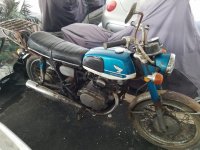
The project is a 1969 CB175 that I bought for $400. It was in extremely rough shape when I got it, needs to be completely restored. I had plans to get it back to as stock as I could but that's going to be cost prohibitive so I've opted to go a semi-custom direction while not altering anything to the point that it can't be put back right if I ever manage to get my hands on correct parts that are missing or parts that I've decided are too far gone to bother with.

Here's what it looked like when I got it:

20200124_094829.jpg


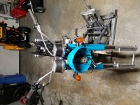
So far I've torn it completely down except for the engine which I'll be starting on once I've gotten the frame and suspension squared away. A lot of my time has been spent striping the old paint, removing rust, and repainting. A substantial amount of time has also gone into polishing aluminum too:

20200802_181257.jpg

20200823_182758.jpg20200829_192827.jpg20200915_193149.jpg
 

Attachments

  • comp_mc.jpg
    comp_mc.jpg
    135.7 KB · Views: 22
Painting looks great! I have the same bike but a year newer, little better shape. Maybe someday I can copy your efforts!
 
I've painted a few more parts. The big effort has been the gas tank. It took me a few attempts to get the dents filled with Bondo before I was satisfied. I painted the tank with many coats of Rustoleum Lagoon enamel spray paint and I applied 3 coats of enamel clear today.

20200928_212843.jpg20201009_135443.jpg

I wasn't originally going to use the stock fenders because they seemed too far gone to do anything with but I gave it a go at getting them to a state where I could use them. I removed the dents on the fender with a combination of hammering, pushing against tire irons secured in a vise, and filling with Bondo. I sprayed them with primer but I haven't decided what color to make them, it'll be either white or the same lagoon color I've been painting everything else.

20201018_152450.jpg

I also painted the headlight ring black as well as the pieces that go between the fork ears and the upper fork covers.

20200919_164734.jpg
 
I've gotten some more painting done since the weather has been pretty warm. I almost have the tank finished, I just need to paint the "Honda" badges. I tried using the same spray paint I used for the tank on the badges but it won't stick. I'm think I may leave them in their raw metal color and just paint the lettering black. I'm not sure what paint to use for the lettering though, I was thinking using one of those little glass jars of model paint and then clear coating the whole badge once the lettering dries. Getting the knee pads back onto the tank was extremely difficult but I got it done. Aside from the badges the only thing the tank needs now is a new gas cap gasket and a new petcock. I have the original petcock but it's pretty cheap to get a shiny reproduction so I'll probably do that. I also painted the fenders since they were extremely corroded and the front fender had no chrome left and was dented.

20201111_185210.jpg
 
Paint looks good! Now that I'm getting the last mechanical parts of my project squared away I'm starting to think about what I'm going to do about painting the rusty gas tank. I really like the color on yours.
 
I’d give it a test now before you get any further but I doubt your paint job is gonna hold up against gas. Most single stage paint just doesn’t cut it when it makes contact with gas.

Just something to think about
 
I’d give it a test now before you get any further but I doubt your paint job is gonna hold up against gas. Most single stage paint just doesn’t cut it when it makes contact with gas.

Just something to think about


I know this wasn't directed at me, but do you know of any spray paint or clear coat that will hold up to gas?
 
Spraymax 2K clear stands up to gas and other solvents by all accounts here. I've not used it myself, but many others here have and with good results. I understand it is very toxic however, so plan to use a respirator when spraying it.
 
What he said. ^^^

Spraymax2k or Eastwood 2k clear both hold up.

Used em many times.

No more toxic than a standard can of spray paint - don’t huff either. People may think it’s harsher because your typically using it in a confined space with limited to no air flow. Where as most people rattle can outside.

Go into your bathroom and unleash a can of spray paint - come back and report how fresh and non toxic your experience was haha.

Protect your brain.
 
I got the front forks together and mounted them on the bike. The original lower fork covers were so rusted I had to cut them to get them off the fork bodies. Luckily I was able to find another pair of forks on eBay with covers in better condition. Still some spots where the chrome is bubbling off but much better than the originals.

20201130_204608.jpg


I got the motor apart after some considerable struggle getting the oil drain bolt unstuck and I'm in the process of cleaning the internals. The motor was caked with massive amounts of dirt and grease.

20201127_173442.jpg20201211_144420.jpg

20201218_194537.jpg20201218_194550.jpg

I replaced the valves, valve springs, and guide seals and leveled the various mating surfaces on the head and the jugs.

20201215_203124.jpg20201219_211107.jpg

I'm planning on measuring the cylinders and pistons for wear to make sure there's enough material left before honing. Hopefully everything will in tolerance, we'll see. As for the crankcase internals, I didn't find any broken gear teeth and there doesn't look to be any horrible wear from what I can tell. I think I will be able to just clean and reassemble with any luck. I did notice the cam chain seems to have cut quite a grove into the cylinder head somehow. I don't know if that means the spring was too weak to hold the tensioner block against the tensioner or it was never adjusted and the vibration just caused the chain to rub against the head causing the groves to be cut into the aluminum. You can see the damage in the bottom of the left picture above.

20201213_152137.jpg20201213_152143.jpg
 
Those "chain tracks" are quite common and simply indicate proper tensioning maintenance wasn't done.....Those aren't even too bad...(I've seen them cut all the way to the plunger shaft hole).......You should be fine.....
 
I finished cleaning all of the engine parts and got the necessary supplies to start reassembly. I tried using the red Scotchbrite wheels on my buffing motor to shine up the cases. They work but they fall apart quickly and throw a ton of dust. Did the best I could with them on the buffer, may do some more by hand later.

I put the crankcase back together today. The hardest part was getting the shift forks back the right way. I'm able to shift through all the gears turning the drum and shafts by hand so I guess that's a good sign? We'll see I guess.

20201231_180225.jpg

I measured the cylinders and found they are still within tolerance but the pistons themselves are a little out of spec. so I got aftermarket replacements.

20201230_164448.jpg

Used Honda bond on the mating surfaces of the two halves of the crankcase and torqued the bolts down per. the shop manual. Strung the new cam chain through and tied it together with a piece of wire so I don't drop it in the bottom end.

20201231_192805.jpg20201231_192814.jpg

I think my next step will be honing the cylinders then installing the pistons.
 
I honed the cylinders using a Flex-Hone and engine oil as lubricant:

20210103_150711.jpg

Cleaned the cylinders up nice and quick. I used to use Flex-Hones all the time when I was an instrument repair technician to clean the insides of brass instruments. Worked really well for that application.

Installed the new pistons and rings:

20210103_155038.jpg

And installed the cylinders:

20210103_170610.jpg

You can see I also got the clutch basket together with new friction plates and installed the oil filter.

Should be installing the head next.
 
I put the breaks together today. I originally planned to rebuild them after I rebuilt the wheels but since I'm waiting for the rims I want to come back in stock, I figured I'd just get it done now. The old rims are structurally sound and they actually don't look too bad but I want shiny new ones to go with the new spokes I got.

20210115_141247.jpg20210116_161950.jpg

I dissembled, cleaned, and repainted the starter motor. I'm waiting for a rebuild kit to come be delivered before I put it back together.

20210117_144127.jpg

Once the starter motor is back together I can install it and close up the shifter side of the engine.
 
Once you get the wheels back together, be sure to check the shoes for proper contact with the drum before putting the wheels back in the frame and forks. Most shoes aren't arced properly out of the box these days and they will have poor stopping power if you don't arc them to the drums.
 
I finished rebuilding the starter motor and tested it out with some jumper cables before installing it. The starter I rebuilt was actually a different starter than came with the bike. On the original I stripped the screws badly so I couldn't get it apart. I stripped the screws by stupidly using my powered impact driver rather than the manual one you hit with the hammer. Guess I was tired and wasn't thinking clearly. Oh well. The original was in much worse shape than the other starter anyway. However, after I rebuilt the new starter, I realized it was slightly shorter than the original. When installed, the body doesn't butt up all the way to where it enters the crankcase. The effect is the gear that drives the starter chain sits too far back and is out of line with the starter clutch gear. To remedy the situation, I put an appropriately thick washer behind the drive gear to line it up with the starter clutch gear. Not an ideal "fix" but I greased the washer up as well as I could and hopefully it'll be fine. Since the starter gear only spins when the starter is spinning, I feel like it shouldn't wear that badly. Ideally, it's only running for a second or two anyway. I could be wrong though...we'll find out I guess.

I installed the stator coil, clutch pusher mechanism thing, and installed the side cover. After doing that, i wanted to test out the function of the clutch. I'm glad I did because when I lifted the thread clutch, the clutch rod pushed in but didn't return. I had to open up the other side cover and I found that the retaining snap ring that holds the clutch basket to the shaft had popped off somehow. Maybe I didn't have it all the way in the grove when I installed it. Once I got it back on and in the grove properly the clutch worked as expected. I'm a bit paranoid that the snap ring is going to come off again at some point. I really don't want to be riding the thing and have the clutch fail like that. I'll have to test it a bunch of times before attempting to ride the thing on the road. Good thing I have a pretty big backyard.

20210122_144504.jpg20210122_204420.jpg
 
A better solution might have been a new snap-ring and checking to insure the "sharp/flat" side is aimed outwards.....
IF you have to ask, phone me..........;)

While I believe you are already aware, there is a height/spacing difference on the two sides of the motor sprocket.....

Untitled.png
 
Last edited:
I put a new snap ring on the transmission shaft where it interfaces with the clutch basket now as suggested. Snapped in more soundly than the old one. Thanks for the tip. I am aware of the two sides of the started motor gear differing. The body of the starter is what's different, the mounting holes don't line up if the motor is pushed all the way into the hole going into the side cover. The real solution I guess would be to get the old starter apart and rebuild that one then use the screws from the replacement starter to replace the stripped ones.
 
I put a new snap ring on the transmission shaft where it interfaces with the clutch basket now as suggested. Snapped in more soundly than the old one. Thanks for the tip.

I'm assuming you did take note of Steve's point that the snap ring has a flat side and a rounded-edge side, and the flat side should be facing out so it can better handle the thrust and not pop out of the groove.
 
I finished up the engine. The last thing I needed to install was the advance mechanism and the points.

20210124_152645.jpg

When installing the little cam that's part of advance mechanism, I watched those guys in Houston collectives video on YouTube. They said that there's a certain way the cam is supposed to be oriented that none of the manuals make mention of. I didn't see any alignment marks like they showed in their video but there video doesn't cover the 175s. To my eyes I don't see how you could install the cam in a "wrong" orientation as both lobes look exactly the same and there's only one contact breaker on my bike. If anyone knows anything about that, I'd appreciate any info. I got the engine into the frame without too much trouble:

20210131_192531.jpg

Also installed a new ignition coil on the frame and filled the engine with oil.
 
I believe the 175 breaker cam can go on either way, but others with more knowledge of them will weigh in. The 350 does have to be oriented correctly because it's a 180° twin, if the breaker cam is put on 180° out the 350 will not run. At least they spoke the truth about that subject.
 
Breaker cam orientation doesn't matter on the single points 360 degree twin engines......
With two lobes @180 degrees apart, installing the breaker cam 180 "out" is the same as installing it "correctly"....
 
Last edited:
I installed the carburetors:

20210206_194349.jpg

I lost a few of the little plastic bits that go on the choke assembly but found some extra plastic I had lying around which fit nicely in their place. The threaded ends of the choke levers that go through the carburetor body were also chewed up so instead of using the regular nuts, I drilled holes through them and installed cotter pins to keep them secured. Seems to work just fine.

I also installed the center stand and the rear brake pedal but I'm up in the air about what I want to ultimately do about the center stand, I may take it off. I don't really like the bulky look of it under the swing-arm. And I can't tell if it's supposed to be tight when its retracted or bounce around? I'd think it should be tight...but mine isn't. Is there some trick with that flat metal lever piece where the spring attaches that I'm missing that makes it tighter when retracted? Maybe my spring is worn out? (When I took it off during disassembly it seemed pretty tight so I don't think it's the spring)

I'm also starting to work on setting up the controls on the handlebars. I'm using aftermarket perches, throttle assembly, and switches so I need to work out the best arrangement that will work. Right now I have the right hand controls going from the end of the handlebars to the center arranged Throttle -> switches -> perch. However, doing this and routing the throttle cable behind the headlight bucket like it was originally set up causes the cable to be pulled when locking the handlebars fully to the left. I'm thinking I should change the order to Throttle -> perch -> switches instead. If I do that, however, it'll be an uncomfortable reach to the switches where I'd have to lift my hand from the throttle. The other option is to leave the order the way it is and not route the throttle cable behind the headlight bucket.

At the same time I'm getting stuff ready to start wiring everything. The wiring harness looks like it's in good shape but it's ugly with the cracked tubing and old electrical tape. I'm going to clean it up as best I can before putting it on the bike. I order a new ignition key switch because the old one looks pretty bad. It might still be functional but the chrome part of it is all rusted and ugly so I'd rather replace it. In general I like the idea of replacing the entire electrical system with new components. I got one of those combo regulator/rectifiers to replace the old rectifier, new points, new ignition coil, new condenser, spark plugs, new battery, new starter solenoid, horn, rebuilt the starter and am using new switches along with aftermarket indicators. The only original electrical component will be the stator coil.

With the battery box, I put some rubber grommets in place of the stock rubber pads (I threw them out like a dummy). The grommets actually work nicely hand hold the battery very securely.

20210205_191327.jpg

So things are moving along. I'd like to know your opinions regarding the center stand issue.
 
Once you get the wheels back together, be sure to check the shoes for proper contact with the drum before putting the wheels back in the frame and forks. Most shoes aren't arced properly out of the box these days and they will have poor stopping power if you don't arc them to the drums.


Don't mean to hijack anybody's thread here, this just caught my eye...wondering if you could elaborate on how you arc new shoes to the drums? In the interest of good manners please let me know if I'm out of order here.
 
Don't mean to hijack anybody's thread here, this just caught my eye...wondering if you could elaborate on how you arc new shoes to the drums? In the interest of good manners please let me know if I'm out of order here.

A brief sidebar on a subject also covered in another's thread is acceptable for informational purposes. I tried to find LDR's instructions on how he did his, with sandpaper glued or taped to the drum and rotating the shoes on the sandpaper, marking the high spots in the linings with a sharpie and sanding them again. It's a process to reshape the arc of the shoes to match the drum for the best drum coverage and resulting grip, in large part because the aftermarket manufacturers don't spend the time to even get them that close anymore. Unfortunately I couldn't find his post about it quickly, but I'll continue to look for it. If it isn't already, it needs to be a sticky anyway.
 
I ran the wiring harness through the frame. I also installed my aftermarket turn signals. I noticed after I installed them however that the headlight bucket was actually dented in on one side where the turn signal stem goes in. To fix the dent I used a large bolt and threaded it into the headlight bucket on the dented side and put it in my vise. Gently pushing back and forth on the headlight bucket I eventually got it to a state that was acceptable to me. Now the turn signals look reasonable in line with each other.

smjall.jpg

I also installed the gauges and ran the clutch and throttle cable to where they need to be. Everything is installed loosely so I can make adjustments when things are more finalized. I put on a new ignition key switch and hooked up the spark plug wires with resistors.

smaally2.jpg

I also received my new rims, tires, tubes, and rim strips, in the mail so I am ready to start assembling the wheels. I bought a wheel truing stand so I can build the wheels properly. I've watched some YouTube videos on wheel lacing and truing and I'd like to tackle the job myself. Doesn't seem like rocket science but I could be wrong. It's something I'll have to take slowly and carefully. At the same time I'm looking for aftermarket control switches that fit in with what I want. I'm trying to make a fairly minimalist setup, the huge honking switch boxes don't appeal to me. I'll have to see what's available and practical, may end up building electrical controls myself.
 

Attachments

  • 20210220_181843.jpg
    20210220_181843.jpg
    166.4 KB · Views: 7
  • 20210220_181843.jpg
    20210220_181843.jpg
    162.6 KB · Views: 7
I haven't put them together yet but they look like they're decent quality at a glance. Hard to say at this point. I will say everything I've bought from 4into1 previously has been good quality and I've had nothing but good experiences with the company. If I have problems I'll definitely note them here.
 
Last edited by a moderator:
I managed to lace the wheels with new spokes and spoke nuts after quite a few tries:

20210319_172405.jpg

I first tried using the new aluminum rims I order but I ended up using the stock steel rims. I decided the the little bit of chrome that bubbled off wasn't really that bad and the lacing went much easier with them vs the aftermarket rims. I also like how much stronger the steel rims feel. I bought a wheel truing stand and did what I felt was a pretty good job managing to get the wheels true side to side and up and down to just a few millimeters.

rim on stand.jpg (Don't know how to rotate this picture, tried in my editor on my computer, still posts like this...)

I got tires and I attempted to install them myself. I was able to get them on the rims fine but I damaged the tubes so instead of trying and screwing up again, I brought them to a motorcycle dealer/shop and had them mount and balance the tires for me:

20210403_141036.jpg

I installed the wheels on the bike for an initial fit check. Seems pretty good so far before any kind of fine adjustment. I do notice on the front wheel brake assembly, the brake shoe seems to just touch the brake drum wall at one spot when spinning the wheel with no brake applied. Ancientdad mentioned earlier in this thread that the new brake shoes should be arced to the drums which I haven't done yet. I'm thinking that once that's been done, the issue will be resolved. Need to read up on how to do the arcing.

20210404_115804.jpg
 
(Don't know how to rotate this picture, tried in my editor on my computer, still posts like this...)

I saved and rotated the picture for you, then replaced the one that was 90° off. If you're using Windows 10, apparently it autocorrects pictures for you and fools you on the orientation of them. Here's some info on why the pics end up that way, it really begins with how they are taken if you're using a phone camera like 90% or more of us these days

https://www.vintagehondatwins.com/forums/showthread.php?507-Pics-post-upside-down

BTW, the bike is coming along nicely.
 
20210530_114633.jpg

Lot's of progress since my last post. I have the electrical system all squared away now, turn signals, headlight, neutral indicator, signal indicator, all work. I replaced and adjusted the points and replaced the rectifier with a modern regulator/rectifier and I'm getting a good spark. Starter motor cranks strong. Also got the clutch adjusted as well as the front brakes. Next step I think is putting the exhaust system on. After that the tank goes on and the fuel lines connected and we'll see if she actually starts.
 

Attachments

  • 20210530_114644.jpg
    20210530_114644.jpg
    197.1 KB · Views: 16
I'm liking that color. IMO, the only thing missing is a stripe of some sort on the tank, but that's one of the harder things to get right.
 
I'm liking that color. IMO, the only thing missing is a stripe of some sort on the tank, but that's one of the harder things to get right.

Or cheat like I did, and use vinyl under the final 2K lacquer …..

9nNtZgh.jpg
 
Honestly, the paint job is probably the worst thing about the project. It's defiantly not done right and probably won't hold up very well. I'm ok with that for now because the fenders were in such bad shape that I had to either get them re-chromed (which I didn't want to spend the money or time on) or just paint them. So I pushed out the dents as best I could, used bondo and sand paper, said good enough and sprayed some Rustoleum enamel paint on then a clear coat. It's cheap and it works for my purposes though. I do think the black/blue color scheme is pretty cool.
 
Honestly, the paint job is probably the worst thing about the project. It's defiantly not done right and probably won't hold up very well. I'm ok with that for now because the fenders were in such bad shape that I had to either get them re-chromed (which I didn't want to spend the money or time on) or just paint them. So I pushed out the dents as best I could, used bondo and sand paper, said good enough and sprayed some Rustoleum enamel paint on then a clear coat. It's cheap and it works for my purposes though. I do think the black/blue color scheme is pretty cool.

Well, the pictures make it at least a good 20 footer (y) :) and I absolutely like the color
 
I initially planned to use reproduction exhaust flanges I bought off 4into1 but unfortunately, they don't actually fit. The inner diameter is far too small for the header pipe. If I had a lathe I would have enlarged them but since I don't, I reused the originals. The originals were completely rusted and after wire brushing as best I could and having them still looking awful, I decided to just paint them. I sprayed them with high temp. engine enamel and they look good enough to me now.

20210607_175445.jpg

The headers themselves are also pretty rough, scratched up and rusty. The majority of the rust is facing towards the engine though so it doesn't bother me too much. I have aftermarket slip on mufflers I want to use but I found that the reducers that come with them don't work with the headers. Still too wide. So I have to figure out some way of taking up the slack between the header outer diameter and the muffler inner diameter. My first thought is to get some of that adhesive backed aluminum they have in roles and wrap the the part of the header that mates with the muffler until there's enough material that the collar that comes with the muffler can be used to tighten the rest of the way. Again, if I had a lathe, I could make a spacer type deal but I'm stuck with whatever I can find. If anybody has any suggestions on what to use to take up the space I'd appreciate the input. Thanks!
 
The 175 headers are ridiculously small. I used a combination of the regular 3 piece reducers and beer/soda can aluminum to take up the the space. I’ve also made homemade reducers from light gauge aluminum stock. If the mufflers don’t have little slices around the header end, you can dremmel 2 or 4 of them, and it’ll allow the muffler end to shrink just a bit. Also get some nice clamps that you can get tight.
 
My solution to make the aftermarket mufflers fit the headers was to use the adhesive aluminum tape I mentioned paired with the adapters that came with the mufflers. I built up the tape on the headers enough so that the adapters would go on snug and then I added some more layers on top of the adapters. Then I tightened down the mufflers with the provided clamps. The results seem tight enough to keep the exhaust from escaping from where header and mufflers connect. (At least I hope so)

20210612_170117.jpg

20210612_170128.jpg

I installed the fuel lines, carburetor overflow tubes, and the gas tank. I do still need to install the tank cross-over fuel line; I ran out of fuel line clamp things so I need to get some more before I do it.

20210613_165004.jpg

20210613_165038.jpg

Once the overflow line is connected, I think I'm ready to see if this thing will actually start. Here's hoping.
 
Back
Top Bottom