
@ballbearian covered this in his build thread starting here. Member 66Sprint (who recently passed) came up with a nice solution to the over advance issue.
-
Don't overlook our Welcome Package, it contains many links to important and helpful information about functions at VHT like posting pictures and sending PMs (private messages), as well as finding the parts you need.
AD
You are using an out of date browser. It may not display this or other websites correctly.
You should upgrade or use an alternative browser.
You should upgrade or use an alternative browser.
1961 CB72 The Long and Winding Road
- Thread starter Pridanc
- Start date
crazypj
Veteran Member
- Joined
- Jun 5, 2020
- Total Posts
- 1,595
- Total likes
- 1,047
The centrifugal filter is actually much more efficient than paper one, particularly if you use more than 6K rpm.
There is a discussion about it on here somewhere
There is a discussion about it on here somewhere
Pridanc
Veteran Member
Hey crazypj,
Thanks for jumping in.
After all the time spent cleaning this little beast, and then reading up on centrifugal filters, I played a game of Roshambo to settle it as I was stuck.
Anyway there's no question a centrifuge is a super interesting way to keep the life blood clean but all said and done, I'm good with my choice here.
Stay well!
crazypj
Veteran Member
- Joined
- Jun 5, 2020
- Total Posts
- 1,595
- Total likes
- 1,047
I had to look up Roshambo, never heard it before. 
ballbearian
Veteran Member
This is a great thread, really enjoying it. The work on cleaning the crank oilways and sludge traps in it were extra special.
The roll pin advance limiters must be holding up ok in mine so far.
The roll pin advance limiters must be holding up ok in mine so far.
Pridanc
Veteran Member
crazy, I only knew it because of my kids. When I grew up it was Rock-Paper-Scissors. You should have seen me trying to spell it. Thank gosh for the net, otherwise it would have been ugly.I had to look up Roshambo, never heard it before.
Pridanc
Veteran Member
#28
By now y'all know that as I leave the head and return to the bottom end, I can't imagine I'm not forgetting something so it'll be no surprise if I go back. If I do, I'll do my best to say I did in case anyone wants to see what googball thing I dropped.
Bottom end and gears.
Before jumping in, my brain has this tease of some little chicklet thing (in the red circle) that can be installed backwards as it can physically go back incorrectly, but am told the mechanism will not work properly or perhaps not as well as it would.. So I'm openly saying I think it is the little chicklet thing mentioned to me and is a part of the kick start mechanism. IF my brain serves me, you can put it in flipped (side to side, not end to end) and it will work but not well? Say I the expert here. As I do not remember if this is the "don't forget" bit that was mentioned to me, just make sure yours goes back together like this and you are covered.

No matter what, keep copious pictures as you take it apart and then put it all back the way you came. As mentioned, non of this is hard so just go slow and if something seems amiss, stop and think about it. Every piece is there for a reason and knowing its job also then means there is only one place it can go.
By now you know that once I've spent the time to get somewhere, like inside an old engine, I'm replacing all the parts that seem slightly too worn. Typically this is bearings, bushings and any seals. If you find parts not too worn in your opinion, you do not have to replace them but I'd replace the seals regardless. Regardless , this is your baby so the decision is yours. As I'm lazy. I tend to do the "out with the old" trick very often. So lets not mention this out-with-the-old to my wife as I rather enjoy being inside my old house. Deal?
Bearings, IMO, are good if not overly sloppy and roll without any glitch's, bumps, or complaints. Again mine felt ok and many passed my smell test, and I have a sensitive nose. One small example is this bush which was visibly worn in this circled area and although it was working at doing its job, it had to go IMO.

Once the lower half of the engine case was pulled of, it was time to clean and inspect. Old engines get nasty with age. OK, so do Old ppl like me.

We've discussed the bearings and bushes, but time to look hard at all those part that make up the transmission. Are the dogs on the gears good? Are the grooves in the shifting drum good? Is any part of the shift forks warn enough to impart slop? Some of this can impede function but equally bad, create imprecision when none was meant to be. In my case, this is a restoration and not just an exploration to catch what was getting long on tooth and then leaving it. A "resto" means making it new again. As I've spent more hours than I want to know exploring a resto, in many ways, is easier. Things that wear tend to have little chance of staying which means less time looking and agonizing. See? EZ-er...for me!

The Shift drum is at the very top. Looks like a rolling pin for small pizzas. Those curvy slots have some pins that ride in them, forcibly moving things around. When you operate the shift lever with your foot, you turn this drum which then moves the forks that select a gear. So look at the slots and the pin end of the bolts. All this is pointed out in purple.
In my experience forks tend to wear at the yellow circles. These can wear in more than just this area but this is typically the first area. Do they have to be perfect, well no, but those forks slide into a groove of two gears (one fork, one gear) as can be seen here above. Follow the blue lines. The half moon shape in the forks fit into the groove you see in the gear here. Just look for wear and if you think it too much, then phone-a-fren who's done this before, OR, look at a few pictures online. FleaBay typically has good pictures to help you decide.
Gears teeth should still have good form. Typically wear appears on one side of each tooth so if you see a side that no longer has the shape of the other side of the same tooth, time to think harder. And look at the dogs. That is the dogs the arrows point to below. (you can also see dogs on the gear above as another point of reference.)
 Dogs are wear items but when these edges get too worn, you may want to replace the gear/gears. As you can see here these edges look sharp and precise. As they wear, these edges grow, as in the radius gets larger and less defined. If you look close, you can see that the sides of the dogs, lets call it their left and right side (not top or bottom?) are tapered in. They have a reverse cut which helps the dogs pull each other together under load. As the edges become rounded corners, there is less and less taper to grab to the dogs become less effective. Oh yes, the still work but shifting may need to be more authoritative with damage and age.
Before I leave this post, I want to mention my gear choices and why. This topic of to X or not to X is well documented. Nonetheless as a bum who's changed too many gears in quick change dog boxes for cars, I have gear charting stuff to take the gear ratio info and stare. These days this is not so innocent as it once was because I now drool. Not from a cool factor but just because. Hey, old dogs drool OK? Sad, I know.
I'm sure this is out there 100 times but what the heck, here it is again. And I've got numbers as well but a graph like this is generally all telling for me. If I need more info to help sway me, then I grab the numbers.

Forgive the blurriness as my computer and I were arguing and it won. However it sure seems to me to be clear enough to get the point across. Two charts are combined here.
One is the OE as delivered gear stack in this engine in all black. The chart with the purple bits is the famed X box. 1st gear and 4th gears are the same so share the same bit of black, but this displays
the new 2nd and 3rd gears and the change they bring in purple. Clearly, the X box has less rpm drop between the lower gears and in hind sight,
this may well be the right choice for many of y'all. But for me, a guy who doesn't care for stop-n-go traffic of a city, the OE box fits my bill for the
gentle rolling hills and curves I prefer. Top 3 gears are closer making it easier to keep the little buzzer on the boil. Like most everything here in the description of my journey, the choice is yours.
And even if you decide later you'd like to give the other stack a try, well step right up as you can! No need to buy any other parts. I will however toss out that this just might fall in the PITA range of things
to do on a Saturday afternoon.
Enjoy your weekend as I'm off to watch more of the LeMans 24. Talk later.
By now y'all know that as I leave the head and return to the bottom end, I can't imagine I'm not forgetting something so it'll be no surprise if I go back. If I do, I'll do my best to say I did in case anyone wants to see what googball thing I dropped.
Bottom end and gears.
Before jumping in, my brain has this tease of some little chicklet thing (in the red circle) that can be installed backwards as it can physically go back incorrectly, but am told the mechanism will not work properly or perhaps not as well as it would.. So I'm openly saying I think it is the little chicklet thing mentioned to me and is a part of the kick start mechanism. IF my brain serves me, you can put it in flipped (side to side, not end to end) and it will work but not well? Say I the expert here. As I do not remember if this is the "don't forget" bit that was mentioned to me, just make sure yours goes back together like this and you are covered.
No matter what, keep copious pictures as you take it apart and then put it all back the way you came. As mentioned, non of this is hard so just go slow and if something seems amiss, stop and think about it. Every piece is there for a reason and knowing its job also then means there is only one place it can go.
By now you know that once I've spent the time to get somewhere, like inside an old engine, I'm replacing all the parts that seem slightly too worn. Typically this is bearings, bushings and any seals. If you find parts not too worn in your opinion, you do not have to replace them but I'd replace the seals regardless. Regardless , this is your baby so the decision is yours. As I'm lazy. I tend to do the "out with the old" trick very often. So lets not mention this out-with-the-old to my wife as I rather enjoy being inside my old house. Deal?
Bearings, IMO, are good if not overly sloppy and roll without any glitch's, bumps, or complaints. Again mine felt ok and many passed my smell test, and I have a sensitive nose. One small example is this bush which was visibly worn in this circled area and although it was working at doing its job, it had to go IMO.
Once the lower half of the engine case was pulled of, it was time to clean and inspect. Old engines get nasty with age. OK, so do Old ppl like me.
We've discussed the bearings and bushes, but time to look hard at all those part that make up the transmission. Are the dogs on the gears good? Are the grooves in the shifting drum good? Is any part of the shift forks warn enough to impart slop? Some of this can impede function but equally bad, create imprecision when none was meant to be. In my case, this is a restoration and not just an exploration to catch what was getting long on tooth and then leaving it. A "resto" means making it new again. As I've spent more hours than I want to know exploring a resto, in many ways, is easier. Things that wear tend to have little chance of staying which means less time looking and agonizing. See? EZ-er...for me!
The Shift drum is at the very top. Looks like a rolling pin for small pizzas. Those curvy slots have some pins that ride in them, forcibly moving things around. When you operate the shift lever with your foot, you turn this drum which then moves the forks that select a gear. So look at the slots and the pin end of the bolts. All this is pointed out in purple.
In my experience forks tend to wear at the yellow circles. These can wear in more than just this area but this is typically the first area. Do they have to be perfect, well no, but those forks slide into a groove of two gears (one fork, one gear) as can be seen here above. Follow the blue lines. The half moon shape in the forks fit into the groove you see in the gear here. Just look for wear and if you think it too much, then phone-a-fren who's done this before, OR, look at a few pictures online. FleaBay typically has good pictures to help you decide.
Gears teeth should still have good form. Typically wear appears on one side of each tooth so if you see a side that no longer has the shape of the other side of the same tooth, time to think harder. And look at the dogs. That is the dogs the arrows point to below. (you can also see dogs on the gear above as another point of reference.)
Dogs are wear items but when these edges get too worn, you may want to replace the gear/gears. As you can see here these edges look sharp and precise. As they wear, these edges grow, as in the radius gets larger and less defined. If you look close, you can see that the sides of the dogs, lets call it their left and right side (not top or bottom?) are tapered in. They have a reverse cut which helps the dogs pull each other together under load. As the edges become rounded corners, there is less and less taper to grab to the dogs become less effective. Oh yes, the still work but shifting may need to be more authoritative with damage and age.Before I leave this post, I want to mention my gear choices and why. This topic of to X or not to X is well documented. Nonetheless as a bum who's changed too many gears in quick change dog boxes for cars, I have gear charting stuff to take the gear ratio info and stare. These days this is not so innocent as it once was because I now drool. Not from a cool factor but just because. Hey, old dogs drool OK? Sad, I know.
I'm sure this is out there 100 times but what the heck, here it is again. And I've got numbers as well but a graph like this is generally all telling for me. If I need more info to help sway me, then I grab the numbers.
Forgive the blurriness as my computer and I were arguing and it won. However it sure seems to me to be clear enough to get the point across. Two charts are combined here.
One is the OE as delivered gear stack in this engine in all black. The chart with the purple bits is the famed X box. 1st gear and 4th gears are the same so share the same bit of black, but this displays
the new 2nd and 3rd gears and the change they bring in purple. Clearly, the X box has less rpm drop between the lower gears and in hind sight,
this may well be the right choice for many of y'all. But for me, a guy who doesn't care for stop-n-go traffic of a city, the OE box fits my bill for the
gentle rolling hills and curves I prefer. Top 3 gears are closer making it easier to keep the little buzzer on the boil. Like most everything here in the description of my journey, the choice is yours.
And even if you decide later you'd like to give the other stack a try, well step right up as you can! No need to buy any other parts. I will however toss out that this just might fall in the PITA range of things
to do on a Saturday afternoon.
Enjoy your weekend as I'm off to watch more of the LeMans 24. Talk later.
Last edited:
crazypj
Veteran Member
- Joined
- Jun 5, 2020
- Total Posts
- 1,595
- Total likes
- 1,047
Suzuki used very similar sprag mechanism for decades on gear change drum. If you asked me which way it went I wouldn't remember without looking at it.
Suzuki had a left and right with offset slot for spring.
Those transmission gears look brand new?
Didn't Honda make a close ratio set for the road race conversion? (and maybe a wide ratio/extra low first gear for desert racers?)
CB72/77 is one of the few motors I've never had in pieces but as the first 'real' bike I ever fell off has a special memory for me. (about 55 years ago)
Pridanc
Veteran Member
You are now punching way over my head. By that I mean there could well be a race sets of ratios and there might even be a 5 speed but those are just whispers to me as I knew that none of that was on my radar even if cool so I did no digging.Suzuki used very similar sprag mechanism for decades on gear change drum. If you asked me which way it went I wouldn't remember without looking at it.
Suzuki had a left and right with offset slot for spring.
Those transmission gears look brand new?
Didn't Honda make a close ratio set for the road race conversion? (and maybe a wide ratio/extra low first gear for desert racers?)
CB72/77 is one of the few motors I've never had in pieces but as the first 'real' bike I ever fell off has a special memory for me. (about 55 years ago)
And yes, those two gear are pictures off of Fleabay. You don't think I had the foresight to take pictures of mine did you? Sad when I set out to take more pictures than you possibly could. Clearly I was off my meds that day. But good eye, as yes. those are spanking new as examples but if you look closely to the one picture of it assembled prior to coming all apart, the dogs look good and were.
Stay well.
Last edited:
Pridanc
Veteran Member
#29
Lets finish up the engine. I realize that for many, rebuilding an engine can be daunting but IMO it needn't be.
If you follow these suggestions , it will be hard to screw up but above all don't doubt yourself! Nothing here is rocket science so take it a step at a time. Read up on the task ahead so when you are doing it, most of it won't be completely foreign to you.
1) Get hold of the shop manual.

I got this manual inside a bunch of info I purchased from Bill Silver. Manuals aside, there is so much interesting info separate from manual I got from BIll I still go back and read them to see what I missed. Simply marvelous information.
2) Make sure you have a parts book. (got it with the Shop manual etc) I've seen some that have too few pages so watch out for those. Bill's is complete for this bike. There are some type-O's in the book but your eyes will not lead you astray. I'd bet all this info can be found here on the forum.

3) Take copious pictures as you disassemble so that if in doubt, you can go to your detailed and plentiful pictures. Do not use me as an example as clearly I didn't follow my own mantra.
4) If / when taking things apart that are known to have small bits that can fall at the most inopportune times, give yourself a safety net. If I have a large area to cover, I use old towels laid down because nothing bounces after hitting a towel so bits wont' get lost. Most common for me is a very large cookie pan with said towel. No matter what you choose, just think about what you'll do IF (when) something sneaks out on its own. BTW , once you know how this engine, or anything your are working on goes together, you will forego the towels. It a process.
5) You can always "phone a friend" aka text or email "those in the know". This very forum as one of those friends so use it. People really like to help so take advantage of that.
As you may now know, the CB72 / 77 crankshafts are made up of 5 pieces and their assembly takes a press and great patience. Think about it. all the pieces need to go together such that all sections are the correct length (and by then, naturally, the OA length of the crank would be in spec), that all parts are "square" to each other, IE, the crank and parts are flat, or perpendicular to each other where it matters and finally, that each part is rotationally in the exact spot. Oh, and DO NOT forget the rods, their needle bearings and cages. I promise that if you did? You'd be so ready to cry.


BTW, it takes lots of pressure to get these parts to become one again. If memory serves 7-10 tons. The moaning of the press is indicative that it is having to work. A lot. My brain hurts to even contemplate doing this. Thankfully my man Tim Miller was well versed. Even if I had the capability to do this, that is a press that was in the 15-20 ton range, not sure I would have attempted it myself. A lot of that is my patience level and nor do I need to learn on the only crankshaft I have. Yes, I am happy to admit that I am a slacker

Old news. Pictures, what pictures? How I don't have a pic of the crank with rods just laying on the bench is beyond me. Sorry.
Now we are going to reverse the steps taken do dismantle the engine. As I haven't done a CB72 before, I'm not sure is there is a huge reason for a specific installation order of these large parts. Just take your time.
Anyway, drop the built-up crankshaft back in making absolutely certain that the bearings fit over their pins in the crankcase. I'm not sure it really matters since this engine had a pin pushed into the case without engaging the bearing as intended ,yet there was no noticeable damage at disassembly. The pins are there for a reason however so there's that. Indeed, this bearing survived and you can see here where this pin got pushed back up followed with some oil-resistant epoxy placed on the pin's back-side hole hoping to keep it in place. Yes, the crank was laid back into the case carefully making sure the pins were in place and that the bearings were all happy.
The picture below sucks (by now, no such a surprise right?) but is an attempt to better show what I'm talking about here. The Red arrow points to the pin that was pushed into the case and was not engaged in the bearing. Angle of the picture doesn't show that the pin is flush with the surface. The green arrow shows a pin still sitting proud as they all are meant to be. And then the epoxy repair to the hole after the pin was pushed back up into place.


Next the gear stacks and as you are doing this, watch that the three seals are nice and happy. One on the crankshaft, one on each of the gearbox shafts. There are only seals on one side of each shaft. The other side of the shafts, the clutch side, all live in oil so no oil seal needed. If the seals end up cocked, this will be as my Dutch friend says: " Not so very good". Truth is, I'm not sure I've ever had a seal **** itself when being trapped by two crankcase halves. Just look at them and if they look close to vertical, you are good. The halves clamping together will have them behave.
After a final clean of the mating surfaces of the two crankcase halves, apply your choice of sealant to the surface staring up at you. (not both surfaces) Like cards its "thin to win" as you want to avoid extra slop. As an old air cooled Porsche guy, I used something called Drei-Bond and or Loctite 574 but don't recall what was used here. But don't panic as there are several great options other than my go to sealants mentioned above as all are excellent: Hondabond (or its equivalents: ThreeBond 1184/1194, Yamabond, or Permatex Moto-Seal.) The only product here I've not used is Permatex Moto-Seal but lets face it, Permatex has an outstanding reputation so again, my thoughts are that each of these will easily get the job done.
Now Drop the Bottom half of the crankcase onto this bunch of bits and voila...we are getting there.

Below is Honda's suggested torqueing sequence for the fasteners of this lower crankcase. Do a search here on the forum as there are some great suggestions that have a suggestions of a different tightening sequence. Of course, you can't go wrong doing it the way Honda did back in the day so if you follow this guide, you are covered regardless. Torques for these is a bit vague so do some spelunking. Again, this forum then "around", as the crankcase torque specs are one of those areas where many points back to general Honda practices (at times I'm not sure what that is) because the original factory manuals are IMO surprisingly vague on the smaller bolts. As I'm a big old chicken, I tend to go slightly under or choose a median value. This I tend to default to a diameter-based approach so M8s are around 15 ft-lbs, M6s 7–10 ft-lbs, always staged in three steps. 1) snug, 2) 50% and 3) use the listed torques mentioned here or what you feel best per forums or others with real knowledge of these. I do not have any hard knowledge but would not hesitate to use the numbers I list. Let your conscience be your guide.

Now you can start adding all the bits that came off prior to splitting the case. And while you are here, don't forget to verify placement and function of the shifting mechanisms. If after full assembly you feel you got it wrong you can always go back and look at it but you'll have to drop the outside the clutch cover which holds oil so be ready for a tsunami of oil. Moral here is to work the shift mechanism before moving on as in change gears etc. Whilst manually changing gears, now might be a great time to install your neutral gear indicator sensor to test on the bench which you may recall lives very near the chain drive sprocket on the right side of the engine? This is a simple on-off switch which activates a lamp in the Nacelle when in neutral.
Here is a picture of the neutral switch installed and regret that the only pic I have is this "pre clean" picture. Nasty.


Gear Selector mechanism. Resplendent in dirt. Dang it all as I've clearly misplaced some photos as I'm not seeing my clean bits. Seriously though, work this and watch how it does its job. Very cool if you ask me. When you are working it, you may have to "jog" the chain sprocket since the engine isn't running so gears are just sitting there.


I'll drop a few more pictures of the before the bottom of the crankcase was dropped back on. I'm so irritated with my lack of pictures at the moment but spilt milk and all... you know the rest.
Reminder here. GREEN words indicate I came back and added something. It is lame here, but I've no doubt I'll be going back and adding sections I forgot, then it will be a sea of green.
Later
Lets finish up the engine. I realize that for many, rebuilding an engine can be daunting but IMO it needn't be.
If you follow these suggestions , it will be hard to screw up but above all don't doubt yourself! Nothing here is rocket science so take it a step at a time. Read up on the task ahead so when you are doing it, most of it won't be completely foreign to you.
1) Get hold of the shop manual.
I got this manual inside a bunch of info I purchased from Bill Silver. Manuals aside, there is so much interesting info separate from manual I got from BIll I still go back and read them to see what I missed. Simply marvelous information.
2) Make sure you have a parts book. (got it with the Shop manual etc) I've seen some that have too few pages so watch out for those. Bill's is complete for this bike. There are some type-O's in the book but your eyes will not lead you astray. I'd bet all this info can be found here on the forum.
3) Take copious pictures as you disassemble so that if in doubt, you can go to your detailed and plentiful pictures. Do not use me as an example as clearly I didn't follow my own mantra.
4) If / when taking things apart that are known to have small bits that can fall at the most inopportune times, give yourself a safety net. If I have a large area to cover, I use old towels laid down because nothing bounces after hitting a towel so bits wont' get lost. Most common for me is a very large cookie pan with said towel. No matter what you choose, just think about what you'll do IF (when) something sneaks out on its own. BTW , once you know how this engine, or anything your are working on goes together, you will forego the towels. It a process.
5) You can always "phone a friend" aka text or email "those in the know". This very forum as one of those friends so use it. People really like to help so take advantage of that.
As you may now know, the CB72 / 77 crankshafts are made up of 5 pieces and their assembly takes a press and great patience. Think about it. all the pieces need to go together such that all sections are the correct length (and by then, naturally, the OA length of the crank would be in spec), that all parts are "square" to each other, IE, the crank and parts are flat, or perpendicular to each other where it matters and finally, that each part is rotationally in the exact spot. Oh, and DO NOT forget the rods, their needle bearings and cages. I promise that if you did? You'd be so ready to cry.
BTW, it takes lots of pressure to get these parts to become one again. If memory serves 7-10 tons. The moaning of the press is indicative that it is having to work. A lot. My brain hurts to even contemplate doing this. Thankfully my man Tim Miller was well versed. Even if I had the capability to do this, that is a press that was in the 15-20 ton range, not sure I would have attempted it myself. A lot of that is my patience level and nor do I need to learn on the only crankshaft I have. Yes, I am happy to admit that I am a slacker
Old news. Pictures, what pictures? How I don't have a pic of the crank with rods just laying on the bench is beyond me. Sorry.
Now we are going to reverse the steps taken do dismantle the engine. As I haven't done a CB72 before, I'm not sure is there is a huge reason for a specific installation order of these large parts. Just take your time.
Anyway, drop the built-up crankshaft back in making absolutely certain that the bearings fit over their pins in the crankcase. I'm not sure it really matters since this engine had a pin pushed into the case without engaging the bearing as intended ,yet there was no noticeable damage at disassembly. The pins are there for a reason however so there's that. Indeed, this bearing survived and you can see here where this pin got pushed back up followed with some oil-resistant epoxy placed on the pin's back-side hole hoping to keep it in place. Yes, the crank was laid back into the case carefully making sure the pins were in place and that the bearings were all happy.
The picture below sucks (by now, no such a surprise right?) but is an attempt to better show what I'm talking about here. The Red arrow points to the pin that was pushed into the case and was not engaged in the bearing. Angle of the picture doesn't show that the pin is flush with the surface. The green arrow shows a pin still sitting proud as they all are meant to be. And then the epoxy repair to the hole after the pin was pushed back up into place.
Next the gear stacks and as you are doing this, watch that the three seals are nice and happy. One on the crankshaft, one on each of the gearbox shafts. There are only seals on one side of each shaft. The other side of the shafts, the clutch side, all live in oil so no oil seal needed. If the seals end up cocked, this will be as my Dutch friend says: " Not so very good". Truth is, I'm not sure I've ever had a seal **** itself when being trapped by two crankcase halves. Just look at them and if they look close to vertical, you are good. The halves clamping together will have them behave.
After a final clean of the mating surfaces of the two crankcase halves, apply your choice of sealant to the surface staring up at you. (not both surfaces) Like cards its "thin to win" as you want to avoid extra slop. As an old air cooled Porsche guy, I used something called Drei-Bond and or Loctite 574 but don't recall what was used here. But don't panic as there are several great options other than my go to sealants mentioned above as all are excellent: Hondabond (or its equivalents: ThreeBond 1184/1194, Yamabond, or Permatex Moto-Seal.) The only product here I've not used is Permatex Moto-Seal but lets face it, Permatex has an outstanding reputation so again, my thoughts are that each of these will easily get the job done.
Now Drop the Bottom half of the crankcase onto this bunch of bits and voila...we are getting there.
Below is Honda's suggested torqueing sequence for the fasteners of this lower crankcase. Do a search here on the forum as there are some great suggestions that have a suggestions of a different tightening sequence. Of course, you can't go wrong doing it the way Honda did back in the day so if you follow this guide, you are covered regardless. Torques for these is a bit vague so do some spelunking. Again, this forum then "around", as the crankcase torque specs are one of those areas where many points back to general Honda practices (at times I'm not sure what that is) because the original factory manuals are IMO surprisingly vague on the smaller bolts. As I'm a big old chicken, I tend to go slightly under or choose a median value. This I tend to default to a diameter-based approach so M8s are around 15 ft-lbs, M6s 7–10 ft-lbs, always staged in three steps. 1) snug, 2) 50% and 3) use the listed torques mentioned here or what you feel best per forums or others with real knowledge of these. I do not have any hard knowledge but would not hesitate to use the numbers I list. Let your conscience be your guide.
Now you can start adding all the bits that came off prior to splitting the case. And while you are here, don't forget to verify placement and function of the shifting mechanisms. If after full assembly you feel you got it wrong you can always go back and look at it but you'll have to drop the outside the clutch cover which holds oil so be ready for a tsunami of oil. Moral here is to work the shift mechanism before moving on as in change gears etc. Whilst manually changing gears, now might be a great time to install your neutral gear indicator sensor to test on the bench which you may recall lives very near the chain drive sprocket on the right side of the engine? This is a simple on-off switch which activates a lamp in the Nacelle when in neutral.
Here is a picture of the neutral switch installed and regret that the only pic I have is this "pre clean" picture. Nasty.
Gear Selector mechanism. Resplendent in dirt. Dang it all as I've clearly misplaced some photos as I'm not seeing my clean bits. Seriously though, work this and watch how it does its job. Very cool if you ask me. When you are working it, you may have to "jog" the chain sprocket since the engine isn't running so gears are just sitting there.
I'll drop a few more pictures of the before the bottom of the crankcase was dropped back on. I'm so irritated with my lack of pictures at the moment but spilt milk and all... you know the rest.
Reminder here. GREEN words indicate I came back and added something. It is lame here, but I've no doubt I'll be going back and adding sections I forgot, then it will be a sea of green.
Later
Attachments
Last edited:
That looks pretty clean to me. My C77 selector was in a much more abused state lolGear Selector mechanism. Resplendent in dirt.
Pridanc
Veteran Member
#30
More engine stuff.
Not that it matters to 99.99% of us, but thought I'd mention that through the years, and for various reasons only known by Honda (not a slam, just me talking) our Type I engines are considered the 180° engines vs. the Type 2 being considered a 360°. This has to do with the crankshaft layout. These choices affect several things in the engine from power delivery to balance and more. See link below for some education.
Those in the know, most definitely not me, have the knowledge and only have to glance at the bike and can say what type engine that bike uses. I have to look at the points cover Rt side of the engine. You know, the cheat sheet.

The engine in this bike is a Type 1 180 degree engine with the "whack a mole" pistons. I don't have an open picture of the Type 2 but you can see the difference here.


I was going to pontificate about "why this firing order over another" but know that a far better explaination sits with much smarter people than I so follow this link to a gent well worth a listen too. In this case he discusses the various differences in vertical twin firing orders which encompasses the Honda Type I and Type 2 by default. His presentations are such that even this cave man gets it. And besides this video, he has many engine related videos you will enjoy, I promise.
Straightened some fins, cleaned 'er on up. OK, lets admit it is cleaner but the backgrounds affect the shine here too.


Couple of more next entry.
More engine stuff.
Not that it matters to 99.99% of us, but thought I'd mention that through the years, and for various reasons only known by Honda (not a slam, just me talking) our Type I engines are considered the 180° engines vs. the Type 2 being considered a 360°. This has to do with the crankshaft layout. These choices affect several things in the engine from power delivery to balance and more. See link below for some education.
Those in the know, most definitely not me, have the knowledge and only have to glance at the bike and can say what type engine that bike uses. I have to look at the points cover Rt side of the engine. You know, the cheat sheet.
The engine in this bike is a Type 1 180 degree engine with the "whack a mole" pistons. I don't have an open picture of the Type 2 but you can see the difference here.
I was going to pontificate about "why this firing order over another" but know that a far better explaination sits with much smarter people than I so follow this link to a gent well worth a listen too. In this case he discusses the various differences in vertical twin firing orders which encompasses the Honda Type I and Type 2 by default. His presentations are such that even this cave man gets it. And besides this video, he has many engine related videos you will enjoy, I promise.
Straightened some fins, cleaned 'er on up. OK, lets admit it is cleaner but the backgrounds affect the shine here too.
Couple of more next entry.
Pridanc
Veteran Member
#31
Couldn't stop and leave you hanging.


Baby steppin'.

Later...!
Couldn't stop and leave you hanging.
Baby steppin'.
Later...!
Looks really good. I see you used 3 base gaskets, was this because of having the cylinder decked or were the piston were a little higher?
Greybeard70
Member
Very educational video, I found it quite interesting. I have watched other videos by the same guy and learn from them also.#30
More engine stuff.
Not that it matters to 99.99% of us, but thought I'd mention that through the years, and for various reasons only known by Honda (not a slam, just me talking) our Type I engines are considered the 180° engines vs. the Type 2 being considered a 360°. This has to do with the crankshaft layout. These choices affect several things in the engine from power delivery to balance and more. See link below for some education.
Those in the know, most definitely not me, have the knowledge and only have to glance at the bike and can say what type engine that bike uses. I have to look at the points cover Rt side of the engine. You know, the cheat sheet.
View attachment 58646
The engine in this bike is a Type 1 180 degree engine with the "whack a mole" pistons. I don't have an open picture of the Type 2 but you can see the difference here.
View attachment 58645View attachment 58647
I was going to pontificate about "why this firing order over another" but know that a far better explaination sits with much smarter people than I so follow this link to a gent well worth a listen too. In this case he discusses the various differences in vertical twin firing orders which encompasses the Honda Type I and Type 2 by default. His presentations are such that even this cave man gets it. And besides this video, he has many engine related videos you will enjoy, I promise.
Straightened some fins, cleaned 'er on up. OK, lets admit it is cleaner but the backgrounds affect the shine here too.
View attachment 58652
View attachment 58654View attachment 58655
View attachment 58656View attachment 58658
View attachment 58659View attachment 58660
View attachment 58661View attachment 58662
View attachment 58663View attachment 58664
View attachment 58665
Couple of more next entry.
Pridanc
Veteran Member
Yes, at some point the head was cut 0.030" which gave pause to consider our goals here. At every turn, OE like and long life so several things transpiredLooks really good. I see you used 3 base gaskets, was this because of having the cylinder decked or were the piston were a little higher?
1) To make block flat and perpendicular, as you've seen the top was cut.
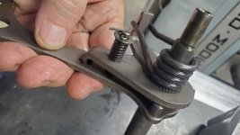
2) Between the head, and the block, the cam timing would now be out with no way to get it back without creating / installing a sprocket that permits timing adjustment like this from Cappellini Moto

the 4 slots allow the bolts to slide unlike the stock gear. This gear is rarely seen without the ignition advancing weights / springs.
3) Although compression wasn't a giant concern, it was a consideration
Those three things combined made the decision to put all the bits back to where the belonged, relative the crankshaft, a no brainer.
Last edited by a moderator:
Pridanc
Veteran Member
#32
I was going to discuss carbs later by why not now as it is an engine ancillary right? And we are kind of, sort of there yes?
I’ve messed with many a carb in my life time ( which does not make me an expert) but because of that, jumping into them does not intimidate me and nor should it you.
Luckily the Keihin Power Jet carbs found on this bike as well as the CB77, is not complicated. The only real difference I can see between the two bikes of this year, are the bore size of the carbs. A Keihin PW22 for the CB72 like this one, and a PW 26 for the 77. Of all the carbs I ever messed with, only the “rack-o-lamb” Honda CBX carbs were what I’d call a pain in the backside. And even then, really only a PITA because of all the added bits these carbs have not to mention the need to keep track of the idle-up feature of the choke mechanism. As we’ve discussed on the engine here, take lots of pictures and have a parts manual beside you. It all goes back together the same as it came apart. I keep a selection of hammers near at all times.
No matter what, IMO, the most important thing you can do is to clean the heck out of them. Each and every part. Prior to actual cleaning these were stripped to the bones with each part catalogued. Cleanliness is paramount to good function and future tunability of your carbs moving forward so spare nothing here. I used solvents, ultrasonic cleaning, fine sanding medium by hand (like 3m Scotch Brite) and some Vapor blasting to finish the outside of the bodies. As I’m chicken about the possibility of getting blasting medium into the passageways, I was very careful about that. Point being, no one thing was used to get them into shape in my case.
 This is before disassembly.
Ironically, I found nothing odd about these carbs internally other than one float bowl had rotted out so was full of holes. I’m told these can be found but none seem available when I look. I know I can have new ones printed as I went down that road but in the interim, I chose fuel proof epoxy.
I ended up with some marine stuff I tested for about a year and still seems OK. I sealed the leaking bowl internally effectively hiding the damage but beyond this. You have to look hard to find the repaired bowl from the outside. Otherwise the only thing I found to be an issue were the float heights.
Left, before clean and repair. Right, cleaned but not yet repaired. Today, it is hard to tell this was ever wonded.


I had to straighten part of the choke lever. As we go through the bike reassembly, this becomes a recurring them. Bend, then re-plate.

Each jet/part should be clean, each hole in every jet or tube should have clear unobstructed passage. Once you are convinced all that is good, and making sure your eyes are covered as a precaution please, go back and squirt carb cleaner through every passage making sure the cleaner comes out on all the places it should. Now blow each passage out with compressed air. It is imperative that the passages are clean. If after close inspection you still have doubt about any jet (or part) , buy new! I’m sure there are some fantastic jet copies out there but for me, the few extra bucks of the real thing give me a greater level of comfort of the new jets being the same as the day this bike was built. Paranoid much? LOL
There are only a few parts that can actually wear out over time and of those, the reality is for just the needle and seat and maybe, just maybe, the throttle slide itself. If you choose to keep the needle and seat you have, test them first. Easiest way for me to test is to install them back into the carb body with their floats and then blow through the fuel line inlet using your mouth as you don’t need much pressure here. The needle and seat only have to stop gravity fed fuel which ends up being very little pressure at the seat. With the float hanging down exerting no pressure on the needle at all, the air from your lungs should flow freely through the needle and seat. Now tilt the carb until the needle is pushed into its seat. Air flow should stop.
If you find your throttle slides have too much wear, which is possible but no common, replace them. Reason being that worn slides pass too much air around themselves creating havoc with the fueling system of the carburetor. I promise that if this is the case, you’ll go crazy trying to tune the idle, off idle, and general low speed running if the engine.
There are times I’ve found that you can eye-ball the float heights with a ruler and your Eye-Ometer. However there are times when, and I feel these baby Hondas with the round floats are it, you might want to purchase or make a tool to more accurately measure the float height. When you have a small bore engine trying to use a slightly large bore carb, low engine RPM doesn’t send the carb good strong signals so confusion can reign. I'm not sure why there are two styles of floats (and float bowls) but mine are the round type so making a tool makes measuring the float height easier and way more accurate. If the floats have flat sides, then this is easily achieved with out modifying your Vernier as I did to get the task done.
The CB72 floats are to be set at or dang close to 26.5mm


Notice the bulbous sides of these floats above? They stop you from using a plane old vernier if not for the extension seen added here. Right hand drawing shows we are measuring h from the surface of the gasket face flat of the body to the top of the float.
Commercial version and I'm sure there are others out there. This one can be found at 4into1.com

As you’ve just cleaned the carbs and they are in hand on the bench, make sure your idle speed screws are all the way out so that the slides can sit at their rock bottom in the carb body. Leave the screw turned out for now and continue assembly.
Jumping ahead to speak more about floats, running the engine for the first time was wonderful except for throttle response. The thing was lean. Jerking the carbs back off and the first thing I checked were the float heights. Sheesh but I must have been coming off of an all-nighter when I first set the floats on the bench because they were off. As in two mm or so. Hard to believe but I’m thinking the gaskets were in place (a no-no and I know better) Oddly when you stand back and think what the heck, how does a few mm mater? Well, it really does most particularly noticeable right off idle as the carb is doing its best to get the engine to pick up revs and then to draw the middle and high speed systems online in an effort to give the engine the fuel it needs at the correct time. If the fuel is too low in the bowl, it take more time and more pull to get the fuel out of the bowl and into the system to be used. Time is the issue here. The engine needs fuel when it needs it, not later.
When looking over the internal parts, do this for the floats as well. When they are in your hand, shake them. Listen for sloshing fuel. If you hear or feel any of that, replace the offending float. Note and as hinted, for some crazy reason, there are two types of floats for these carbs so snag the style you have.
Between us? Having spent some years using electronic fuel injection, I smilingly call a carburetor a “controlled leak”. Carbs are dead simple and in a pinch, I prefer them as it is hard to get one to fail but boy howdy can they be ornery to tune at times. Don’t forget that Honda and Keihin have done the heavy lifting here so all we need to do is to put things, like float levels, back where they belong all nice and clean like.
After the carbs were on the bike, I fed some fuel to it and the bike fired up almost instantly. BTW, hanging a small fuel container nearby gives you far greater access to the carbs just in case. You know, in case its best to remove them again. The CB’s fuel tank hides a lot even though you can still work and tune with the OE tank in place. As you may recall, we set the carb slide as low as they’d go so when you fire the engine, you will have to hold the throttle up a bit whilst allowing time for the engine to warm. A warm engine prefers a slightly different “tune” than a cold one so don’t rush it. Last I checked, the engines are nice and warm when we ride them right?
Back to the basics:
1) check, and set if needed, valve clearance.
2) check, and set if necessary, the ignition timing. Once those are known and you are happy, proceed with the carb!
4) Now with the carbs bolted onto the engine, with good O rings on carb and manifold, verify your needle position one more time is there is any concern. So long as they are the same, proceed. In my case, I have my 22402 needles at second richest setting.

As can be seen here, my clip is in the slot position of the red arrow which raises the needles up in the slide to the second highest slot. In my case, I might even try the needle as high as it will go (last slot to the right of the arrow) but I’m getting ahead of myself. Needle height is a quick and easy change.
Once both slides are in, now it is time to mess with the throttle cables and how the slides respond to the twist of your wrist. (And yes, Keith Code’s books called A Twist of the Wrist are well worth the read) The goal here is to have both slides lift together. This is easy to do using your hand to touch the slides as you gently twist the throttle grip.
.jpg")
To get both slides to raise together, simply go to the adjuster on the carb that is not moving up when the other one does! Won’t take a lot, and before you know it, both slides move at the same time when opening the throttle.
The small screwdriver at the top of the pict is touching the adjuster. Raising the adjuster forces the carb slide to raise earlier because you've removed a bit of slack. Again, this rarely take a lot of adjustment.
.jpg")
Now the fun part. Once the engine is finally warm, turn in the idle speed screws (brass screw as seen above which looks like the cable luber is pointing to) until the engine is idling about where it ought to be. The manual says below 1000 rpm but me, I like a little more. Make sure you have raised the slides by their screws equally for this first swing at it until you can let go of the throttle and the engine will idle by itself.
Now you need to "balance" the carbs. That means that each cylinder is doing roughly the same work. There are tools to really get this close but you can come dang close yourself without the tools by feeling for equal exhaust pulsing or by the sound of using a 3/4” tube in your ear held at right angles to the carb throat. Like the feeling exhaust pulses, adjust carbs to provide the same sound from each carb. I swear, works well.

 Tried to find the "stick" guy again to give him a shout out but of course....What Guy? Kudos to him.
On the left, the commercially available Uni-Syn. Works well, super easy to use. Just place and hold it onto the front opening of the carb and watch the little red indicator move. The goal is to make the red indicator be at the same level of that vertical clear tube for each carb. Now on the right, this is something new to me which I found whilst looking around I saw this and LOVE its simplicity though I’ve never tried it. You use a couple of sticks stuck into each carb levered under the open leading edge of the slide. As you move the slide up or down, the sticks move up and down. When sticks are at the same level, you are golden. Again, I’ve never used it but love the idea. Between the tubes in my ears, tools like the Uni-Syn or sticks along with the ability to feel the exhaust pulsing, I’m covered. You will be too.
Once you have an acceptable idle all “synched up”, now mess with your idle mixture screws. Again, some brass looking screws seen in the GREEN circle. These are angled up slightly. The Red circle shows the engine speed adjuster.
This little baby in the green circle adjusts the air/fuel mixture at idle and can raise and lower the RPM. Most people suggest turning it in or out to find the highest RPM which I do at times but often once I've found that sweet spot, I then turn the screw back in 1/8th to 1/4 turn. (this is richer). This will most likely lose you a few rpm but often I find the gains of off idle response is a worth while trade. Unlike most cars and many motorcycles, there is no accelerator pump to help the carb/engine through this tough area of carburation. YMMV so give it a whirl and settle on what works best for you.

Once you are happy with the mixture, you will most likely want to go back and set the idle speed to what you want which is where you may have been initially. Make sure you adjust the idle speed screws equally but feel free to re-visit the synching thing if you feel you messed it up. Remember? Ear, Vacuum, Sticks, exhaust pulsing, all quick and simple to do.
Now, shut the engine down and with your hand, check that the slides still move together. Very often you’ll find that this has changed because your idle speed screw is holding one slide higher than it did when we started. (Don't forget the slides were sitting on the floor of the carb body when we began) Changing the idles screws typically raises one slide higher than the next putting cable slack into that side. So like before, just take the slack out again with the adjuster on top of the carb. This can be a bit of a tap dance but no matter what, it is all very easy.
OK, I'm toast for now so....Later!
PS, if someone has a nice float bowl no longer wanted....feel free to reach out. I'm trusting the Epoxy but there's always a but... TY
I was going to discuss carbs later by why not now as it is an engine ancillary right? And we are kind of, sort of there yes?
I’ve messed with many a carb in my life time ( which does not make me an expert) but because of that, jumping into them does not intimidate me and nor should it you.
Luckily the Keihin Power Jet carbs found on this bike as well as the CB77, is not complicated. The only real difference I can see between the two bikes of this year, are the bore size of the carbs. A Keihin PW22 for the CB72 like this one, and a PW 26 for the 77. Of all the carbs I ever messed with, only the “rack-o-lamb” Honda CBX carbs were what I’d call a pain in the backside. And even then, really only a PITA because of all the added bits these carbs have not to mention the need to keep track of the idle-up feature of the choke mechanism. As we’ve discussed on the engine here, take lots of pictures and have a parts manual beside you. It all goes back together the same as it came apart. I keep a selection of hammers near at all times.
No matter what, IMO, the most important thing you can do is to clean the heck out of them. Each and every part. Prior to actual cleaning these were stripped to the bones with each part catalogued. Cleanliness is paramount to good function and future tunability of your carbs moving forward so spare nothing here. I used solvents, ultrasonic cleaning, fine sanding medium by hand (like 3m Scotch Brite) and some Vapor blasting to finish the outside of the bodies. As I’m chicken about the possibility of getting blasting medium into the passageways, I was very careful about that. Point being, no one thing was used to get them into shape in my case.
This is before disassembly. Ironically, I found nothing odd about these carbs internally other than one float bowl had rotted out so was full of holes. I’m told these can be found but none seem available when I look. I know I can have new ones printed as I went down that road but in the interim, I chose fuel proof epoxy.
I ended up with some marine stuff I tested for about a year and still seems OK. I sealed the leaking bowl internally effectively hiding the damage but beyond this. You have to look hard to find the repaired bowl from the outside. Otherwise the only thing I found to be an issue were the float heights.
Left, before clean and repair. Right, cleaned but not yet repaired. Today, it is hard to tell this was ever wonded.
I had to straighten part of the choke lever. As we go through the bike reassembly, this becomes a recurring them. Bend, then re-plate.
Each jet/part should be clean, each hole in every jet or tube should have clear unobstructed passage. Once you are convinced all that is good, and making sure your eyes are covered as a precaution please, go back and squirt carb cleaner through every passage making sure the cleaner comes out on all the places it should. Now blow each passage out with compressed air. It is imperative that the passages are clean. If after close inspection you still have doubt about any jet (or part) , buy new! I’m sure there are some fantastic jet copies out there but for me, the few extra bucks of the real thing give me a greater level of comfort of the new jets being the same as the day this bike was built. Paranoid much? LOL
There are only a few parts that can actually wear out over time and of those, the reality is for just the needle and seat and maybe, just maybe, the throttle slide itself. If you choose to keep the needle and seat you have, test them first. Easiest way for me to test is to install them back into the carb body with their floats and then blow through the fuel line inlet using your mouth as you don’t need much pressure here. The needle and seat only have to stop gravity fed fuel which ends up being very little pressure at the seat. With the float hanging down exerting no pressure on the needle at all, the air from your lungs should flow freely through the needle and seat. Now tilt the carb until the needle is pushed into its seat. Air flow should stop.
If you find your throttle slides have too much wear, which is possible but no common, replace them. Reason being that worn slides pass too much air around themselves creating havoc with the fueling system of the carburetor. I promise that if this is the case, you’ll go crazy trying to tune the idle, off idle, and general low speed running if the engine.
There are times I’ve found that you can eye-ball the float heights with a ruler and your Eye-Ometer. However there are times when, and I feel these baby Hondas with the round floats are it, you might want to purchase or make a tool to more accurately measure the float height. When you have a small bore engine trying to use a slightly large bore carb, low engine RPM doesn’t send the carb good strong signals so confusion can reign. I'm not sure why there are two styles of floats (and float bowls) but mine are the round type so making a tool makes measuring the float height easier and way more accurate. If the floats have flat sides, then this is easily achieved with out modifying your Vernier as I did to get the task done.
The CB72 floats are to be set at or dang close to 26.5mm
Notice the bulbous sides of these floats above? They stop you from using a plane old vernier if not for the extension seen added here. Right hand drawing shows we are measuring h from the surface of the gasket face flat of the body to the top of the float.
Commercial version and I'm sure there are others out there. This one can be found at 4into1.com
As you’ve just cleaned the carbs and they are in hand on the bench, make sure your idle speed screws are all the way out so that the slides can sit at their rock bottom in the carb body. Leave the screw turned out for now and continue assembly.
Jumping ahead to speak more about floats, running the engine for the first time was wonderful except for throttle response. The thing was lean. Jerking the carbs back off and the first thing I checked were the float heights. Sheesh but I must have been coming off of an all-nighter when I first set the floats on the bench because they were off. As in two mm or so. Hard to believe but I’m thinking the gaskets were in place (a no-no and I know better) Oddly when you stand back and think what the heck, how does a few mm mater? Well, it really does most particularly noticeable right off idle as the carb is doing its best to get the engine to pick up revs and then to draw the middle and high speed systems online in an effort to give the engine the fuel it needs at the correct time. If the fuel is too low in the bowl, it take more time and more pull to get the fuel out of the bowl and into the system to be used. Time is the issue here. The engine needs fuel when it needs it, not later.
When looking over the internal parts, do this for the floats as well. When they are in your hand, shake them. Listen for sloshing fuel. If you hear or feel any of that, replace the offending float. Note and as hinted, for some crazy reason, there are two types of floats for these carbs so snag the style you have.
Between us? Having spent some years using electronic fuel injection, I smilingly call a carburetor a “controlled leak”. Carbs are dead simple and in a pinch, I prefer them as it is hard to get one to fail but boy howdy can they be ornery to tune at times. Don’t forget that Honda and Keihin have done the heavy lifting here so all we need to do is to put things, like float levels, back where they belong all nice and clean like.
After the carbs were on the bike, I fed some fuel to it and the bike fired up almost instantly. BTW, hanging a small fuel container nearby gives you far greater access to the carbs just in case. You know, in case its best to remove them again. The CB’s fuel tank hides a lot even though you can still work and tune with the OE tank in place. As you may recall, we set the carb slide as low as they’d go so when you fire the engine, you will have to hold the throttle up a bit whilst allowing time for the engine to warm. A warm engine prefers a slightly different “tune” than a cold one so don’t rush it. Last I checked, the engines are nice and warm when we ride them right?
Back to the basics:
1) check, and set if needed, valve clearance.
2) check, and set if necessary, the ignition timing. Once those are known and you are happy, proceed with the carb!
4) Now with the carbs bolted onto the engine, with good O rings on carb and manifold, verify your needle position one more time is there is any concern. So long as they are the same, proceed. In my case, I have my 22402 needles at second richest setting.
As can be seen here, my clip is in the slot position of the red arrow which raises the needles up in the slide to the second highest slot. In my case, I might even try the needle as high as it will go (last slot to the right of the arrow) but I’m getting ahead of myself. Needle height is a quick and easy change.
Once both slides are in, now it is time to mess with the throttle cables and how the slides respond to the twist of your wrist. (And yes, Keith Code’s books called A Twist of the Wrist are well worth the read) The goal here is to have both slides lift together. This is easy to do using your hand to touch the slides as you gently twist the throttle grip.
To get both slides to raise together, simply go to the adjuster on the carb that is not moving up when the other one does! Won’t take a lot, and before you know it, both slides move at the same time when opening the throttle.
The small screwdriver at the top of the pict is touching the adjuster. Raising the adjuster forces the carb slide to raise earlier because you've removed a bit of slack. Again, this rarely take a lot of adjustment.
Now the fun part. Once the engine is finally warm, turn in the idle speed screws (brass screw as seen above which looks like the cable luber is pointing to) until the engine is idling about where it ought to be. The manual says below 1000 rpm but me, I like a little more. Make sure you have raised the slides by their screws equally for this first swing at it until you can let go of the throttle and the engine will idle by itself.
Now you need to "balance" the carbs. That means that each cylinder is doing roughly the same work. There are tools to really get this close but you can come dang close yourself without the tools by feeling for equal exhaust pulsing or by the sound of using a 3/4” tube in your ear held at right angles to the carb throat. Like the feeling exhaust pulses, adjust carbs to provide the same sound from each carb. I swear, works well.
Tried to find the "stick" guy again to give him a shout out but of course....What Guy? Kudos to him.On the left, the commercially available Uni-Syn. Works well, super easy to use. Just place and hold it onto the front opening of the carb and watch the little red indicator move. The goal is to make the red indicator be at the same level of that vertical clear tube for each carb. Now on the right, this is something new to me which I found whilst looking around I saw this and LOVE its simplicity though I’ve never tried it. You use a couple of sticks stuck into each carb levered under the open leading edge of the slide. As you move the slide up or down, the sticks move up and down. When sticks are at the same level, you are golden. Again, I’ve never used it but love the idea. Between the tubes in my ears, tools like the Uni-Syn or sticks along with the ability to feel the exhaust pulsing, I’m covered. You will be too.
Once you have an acceptable idle all “synched up”, now mess with your idle mixture screws. Again, some brass looking screws seen in the GREEN circle. These are angled up slightly. The Red circle shows the engine speed adjuster.
This little baby in the green circle adjusts the air/fuel mixture at idle and can raise and lower the RPM. Most people suggest turning it in or out to find the highest RPM which I do at times but often once I've found that sweet spot, I then turn the screw back in 1/8th to 1/4 turn. (this is richer). This will most likely lose you a few rpm but often I find the gains of off idle response is a worth while trade. Unlike most cars and many motorcycles, there is no accelerator pump to help the carb/engine through this tough area of carburation. YMMV so give it a whirl and settle on what works best for you.
Once you are happy with the mixture, you will most likely want to go back and set the idle speed to what you want which is where you may have been initially. Make sure you adjust the idle speed screws equally but feel free to re-visit the synching thing if you feel you messed it up. Remember? Ear, Vacuum, Sticks, exhaust pulsing, all quick and simple to do.
Now, shut the engine down and with your hand, check that the slides still move together. Very often you’ll find that this has changed because your idle speed screw is holding one slide higher than it did when we started. (Don't forget the slides were sitting on the floor of the carb body when we began) Changing the idles screws typically raises one slide higher than the next putting cable slack into that side. So like before, just take the slack out again with the adjuster on top of the carb. This can be a bit of a tap dance but no matter what, it is all very easy.
OK, I'm toast for now so....Later!
PS, if someone has a nice float bowl no longer wanted....feel free to reach out. I'm trusting the Epoxy but there's always a but... TY
Last edited:
Hans Freekit
Well-known Member
Awesome description. Kudos.#32
I was going to discuss carbs later by why not now as it is an engine ancillary right? And we are kind of, sort of there yes?
I’ve messed with many a carb in my life time ( which does not make me an expert) but because of that, jumping into them does not intimidate me and nor should it you.
Luckily the Keihin Power Jet carbs found on this bike as well as the CB77, is not complicated. The only real difference I can see between the two bikes of this year, are the bore size of the carbs. A Keihin PW22 for the CB72 like this one, and a PW 26 for the 77. Of all the carbs I ever messed with, only the “rack-o-lamb” Honda CBX carbs were what I’d call a pain in the backside. And even then, really only a PITA because of all the added bits these carbs have not to mention the need to keep track of the idle-up feature of the choke mechanism. As we’ve discussed on the engine here, take lots of pictures and have a parts manual beside you. It all goes back together the same as it came apart. I keep a selection of hammers near at all times.
No matter what, IMO, the most important thing you can do is to clean the heck out of them. Each and every part. Prior to actual cleaning these were stripped to the bones with each part catalogued. Cleanliness is paramount to good function and future tunability of your carbs moving forward so spare nothing here. I used solvents, ultrasonic cleaning, fine sanding medium by hand (like 3m Scotch Brite) and some Vapor blasting to finish the outside of the bodies. As I’m chicken about the possibility of getting blasting medium into the passageways, I was very careful about that. Point being, no one thing was used to get them into shape in my case.
View attachment 58684This is before disassembly. View attachment 58682
Ironically, I found nothing odd about these carbs internally other than one float bowl had rotted out so was full of holes. I’m told these can be found but none seem available when I look. I know I can have new ones printed as I went down that road but in the interim, I chose fuel proof epoxy.
I ended up with some marine stuff I tested for about a year and still seems OK. I sealed the leaking bowl internally effectively hiding the damage but beyond this. You have to look hard to find the repaired bowl from the outside. Otherwise the only thing I found to be an issue were the float heights.
Left, before clean and repair. Right, cleaned but not yet repaired. Today, it is hard to tell this was ever wonded.
View attachment 58683
View attachment 58686
I had to straighten part of the choke lever. As we go through the bike reassembly, this becomes a recurring them. Bend, then re-plate.
View attachment 58687
Each jet/part should be clean, each hole in every jet or tube should have clear unobstructed passage. Once you are convinced all that is good, and making sure your eyes are covered as a precaution please, go back and squirt carb cleaner through every passage making sure the cleaner comes out on all the places it should. Now blow each passage out with compressed air. It is imperative that the passages are clean. If after close inspection you still have doubt about any jet (or part) , buy new! I’m sure there are some fantastic jet copies out there but for me, the few extra bucks of the real thing give me a greater level of comfort of the new jets being the same as the day this bike was built. Paranoid much? LOL
There are only a few parts that can actually wear out over time and of those, the reality is for just the needle and seat and maybe, just maybe, the throttle slide itself. If you choose to keep the needle and seat you have, test them first. Easiest way for me to test is to install them back into the carb body with their floats and then blow through the fuel line inlet using your mouth as you don’t need much pressure here. The needle and seat only have to stop gravity fed fuel which ends up being very little pressure at the seat. With the float hanging down exerting no pressure on the needle at all, the air from your lungs should flow freely through the needle and seat. Now tilt the carb until the needle is pushed into its seat. Air flow should stop.
If you find your throttle slides have too much wear, which is possible but no common, replace them. Reason being that worn slides pass too much air around themselves creating havoc with the fueling system of the carburetor. I promise that if this is the case, you’ll go crazy trying to tune the idle, off idle, and general low speed running if the engine.
There are times I’ve found that you can eye-ball the float heights with a ruler and your Eye-Ometer. However there are times when, and I feel these baby Hondas with the round floats are it, you might want to purchase or make a tool to more accurately measure the float height. When you have a small bore engine trying to use a slightly large bore carb, low engine RPM doesn’t send the carb good strong signals so confusion can reign. I'm not sure why there are two styles of floats (and float bowls) but mine are the round type so making a tool makes measuring the float height easier and way more accurate. If the floats have flat sides, then this is easily achieved with out modifying your Vernier as I did to get the task done.
The CB72 floats are to be set at or dang close to 26.5mm
View attachment 58689 View attachment 58691
Notice the bulbous sides of these floats above? They stop you from using a plane old vernier if not for the extension seen added here. Right hand drawing shows we are measuring h from the surface of the gasket face flat of the body to the top of the float.
Commercial version and I'm sure there are others out there. This one can be found at 4into1.com
View attachment 58690
As you’ve just cleaned the carbs and they are in hand on the bench, make sure your idle speed screws are all the way out so that the slides can sit at their rock bottom in the carb body. Leave the screw turned out for now and continue assembly.
Jumping ahead to speak more about floats, running the engine for the first time was wonderful except for throttle response. The thing was lean. Jerking the carbs back off and the first thing I checked were the float heights. Sheesh but I must have been coming off of an all-nighter when I first set the floats on the bench because they were off. As in two mm or so. Hard to believe but I’m thinking the gaskets were in place (a no-no and I know better) Oddly when you stand back and think what the heck, how does a few mm mater? Well, it really does most particularly noticeable right off idle as the carb is doing its best to get the engine to pick up revs and then to draw the middle and high speed systems online in an effort to give the engine the fuel it needs at the correct time. If the fuel is too low in the bowl, it take more time and more pull to get the fuel out of the bowl and into the system to be used. Time is the issue here. The engine needs fuel when it needs it, not later.
When looking over the internal parts, do this for the floats as well. When they are in your hand, shake them. Listen for sloshing fuel. If you hear or feel any of that, replace the offending float. Note and as hinted, for some crazy reason, there are two types of floats for these carbs so snag the style you have.
Between us? Having spent some years using electronic fuel injection, I smilingly call a carburetor a “controlled leak”. Carbs are dead simple and in a pinch, I prefer them as it is hard to get one to fail but boy howdy can they be ornery to tune at times. Don’t forget that Honda and Keihin have done the heavy lifting here so all we need to do is to put things, like float levels, back where they belong all nice and clean like.
After the carbs were on the bike, I fed some fuel to it and the bike fired up almost instantly. BTW, hanging a small fuel container nearby gives you far greater access to the carbs just in case. You know, in case its best to remove them again. The CB’s fuel tank hides a lot even though you can still work and tune with the OE tank in place. As you may recall, we set the carb slide as low as they’d go so when you fire the engine, you will have to hold the throttle up a bit whilst allowing time for the engine to warm. A warm engine prefers a slightly different “tune” than a cold one so don’t rush it. Last I checked, the engines are nice and warm when we ride them right?
Back to the basics:
1) check, and set if needed, valve clearance.
2) check, and set if necessary, the ignition timing. Once those are known and you are happy, proceed with the carb!
4) Now with the carbs bolted onto the engine, with good O rings on carb and manifold, verify your needle position one more time is there is any concern. So long as they are the same, proceed. In my case, I have my 22402 needles at second richest setting.
View attachment 58692
As can be seen here, my clip is in the slot position of the red arrow which raises the needles up in the slide to the second highest slot. In my case, I might even try the needle as high as it will go (last slot to the right of the arrow) but I’m getting ahead of myself. Needle height is a quick and easy change.
Once both slides are in, now it is time to mess with the throttle cables and how the slides respond to the twist of your wrist. (And yes, Keith Code’s books called A Twist of the Wrist are well worth the read) The goal here is to have both slides lift together. This is easy to do using your hand to touch the slides as you gently twist the throttle grip.
View attachment 58693
To get both slides to raise together, simply go to the adjuster on the carb that is not moving up when the other one does! Won’t take a lot, and before you know it, both slides move at the same time when opening the throttle.
The small screwdriver at the top of the pict is touching the adjuster. Raising the adjuster forces the carb slide to raise earlier because you've removed a bit of slack. Again, this rarely take a lot of adjustment.
View attachment 58694
Now the fun part. Once the engine is finally warm, turn in the idle speed screws (brass screw as seen above which looks like the cable luber is pointing to) until the engine is idling about where it ought to be. The manual says below 1000 rpm but me, I like a little more. Make sure you have raised the slides by their screws equally for this first swing at it until you can let go of the throttle and the engine will idle by itself.
Now you need to "balance" the carbs. That means that each cylinder is doing roughly the same work. There are tools to really get this close but you can come dang close yourself without the tools by feeling for equal exhaust pulsing or by the sound of using a 3/4” tube in your ear held at right angles to the carb throat. Like the feeling exhaust pulses, adjust carbs to provide the same sound from each carb. I swear, works well.
View attachment 58695 View attachment 58696Tried to find the "stick" guy again to give him a shout out but of course....What Guy? Kudos to him.
On the left, the commercially available Uni-Syn. Works well, super easy to use. Just place and hold it onto the front opening of the carb and watch the little red indicator move. The goal is to make the red indicator be at the same level of that vertical clear tube for each carb. Now on the right, this is something new to me which I found whilst looking around I saw this and LOVE its simplicity though I’ve never tried it. You use a couple of sticks stuck into each carb levered under the open leading edge of the slide. As you move the slide up or down, the sticks move up and down. When sticks are at the same level, you are golden. Again, I’ve never used it but love the idea. Between the tubes in my ears, tools like the Uni-Syn or sticks along with the ability to feel the exhaust pulsing, I’m covered. You will be too.
Once you have an acceptable idle all “synched up”, now mess with your idle mixture screws. Again, some brass looking screws seen in the GREEN circle. These are angled up slightly. The Red circle shows the engine speed adjuster.
This little baby in the green circle adjusts the air/fuel mixture at idle and can raise and lower the RPM. Most people suggest turning it in or out to find the highest RPM which I do at times but often once I've found that sweet spot, I then turn the screw back in 1/8th to 1/4 turn. (this is richer). This will most likely lose you a few rpm but often I find the gains of off idle response is a worth while trade. Unlike most cars and many motorcycles, there is no accelerator pump to help the carb/engine through this tough area of carburation. YMMV so give it a whirl and settle on what works best for you.
View attachment 58699
Once you are happy with the mixture, you will most likely want to go back and set the idle speed to what you want which is where you may have been initially. Make sure you adjust the idle speed screws equally but feel free to re-visit the synching thing if you feel you messed it up. Remember? Ear, Vacuum, Sticks, exhaust pulsing, all quick and simple to do.
Now, shut the engine down and with your hand, check that the slides still move together. Very often you’ll find that this has changed because your idle speed screw is holding one slide higher than it did when we started. (Don't forget the slides were sitting on the floor of the carb body when we began) Changing the idles screws typically raises one slide higher than the next putting cable slack into that side. So like before, just take the slack out again with the adjuster on top of the carb. This can be a bit of a tap dance but no matter what, it is all very easy.
OK, I'm toast for now so....Later!
PS, if someone has a nice float bowl no longer wanted....feel free to reach out. I'm trusting the Epoxy but there's always a but... TY
Pridanc
Veteran Member
#32 addendum
First off, sorry to have gone silent but as I age, so do those around me and we've needed to help family. My apologies
So, after all my blathering above about carbs, I did order some larger pilot jets. I have gone from a #35 to a 38. I just didn't like the initial throttle response right off idle which we all know can be affected by a myriad of things (remember: Carb=controlled leak) but at this juncture I knew that this wasn't so large as to stop me from adjusting around it with the idle mixture screw. With the 35's the idle mixture screw was maybe 1/8th turn out from bottomed.
As I didn't have the correct short stubby screwdriver with the correct blade to safely grab the pilot jets with the carbs still on the engine, I pulled the carbs and got 'er done. However after putting the carbs back onto the engine, followed by the slides back into the bodies, I casually checked the slides lifting equally as they were prior to this recent removal. Wow, good thing I did as I once again tripped over what was now an issue. Even though I'd had this issue before, I did not recognize it as one. Humbug.
Long story...even longer...the left carb was now clearly hanging up. To be more accurate, its slide was again way behind the right carb's slide. On the surface we can easily take the slack up with the carb/cable adjuster and I did. But this always left the slide raised off its Idle Screw (not good) even if the slide now rose with the other. WT absolute heck was going on? How is that even possible. As mentioned, this had happened before but whilst messing with the carbs/cables the issue cleared itself unbeknownst to me so I thought I was golden. Again, I'd no idea there was even a potential issue until pulling the carbs for the jet change. Not happy that this was now an issue, but happy that I did as I now realized I had an issue and must address it. Dodged a bullet here I think.
So lets now discuss how I addressed it and along the way, please remember I've never seen or touched an old CB before so as I dismantled it, I did my best to copy or emulate what was. This, to me, might be one of those times when what I found was never right. Again, say I, the expert.
Completely flummoxed, it was time to start with the absolute basics. Pull the carbs off, along with the entire throttle-cable system. Dismantle and start measuring every part.
As this picture of a throttle cable control system is a good one, I felt I'd use it even if it is not from this CB72 but from an old BMW. It is great for our purposes here. The Honda "parts picture" of this is sketchy at best.

In my case, the cap of the splitter seen here #16, and the body #14, are swapped around. That is, the cap #16 of the splitter on this Honda receives the single cable #12 from the throttle itself and the lower part of the body has the two carb cable housing receivers. Now, drum roll, the "shuttle" #15 is way different on this Honda. For reference, this bike came with an aluminum splitter which is what I kept. Back to the "if it can be salvaged or reused", I will do that.
My concern here is that the Honda's #15 is a 5mm thick disc (fat washer) seen below that fits very loosely in the housing #14. Even if we can say this is unlikely, the disc can **** which can't be OK by any measure.

Now take a look at the #15 of the BMW which is significantly longer leaving it impossible to **** in the splitter tube. Because of this I drew up and then printed a copy of the BMW part to fit the Honda's aluminum splitter. Is this new part "better", I'm not sure here, but can it help add one more layer of accuracy whilst removing the chance of a tilt? It sure can, and so far it works a charm! Here are some drawings of it.


The original Honda "disc" measured 5.2mm long with a diameter of 10.4mm. The new part's overall length is now 13mm and the diameter is now 11.1mm. The new shuttle is not tight but the good news is that the plastic has almost zero expansion with heat where as the aluminum tube will expand without question. Plastics slide on aluminum all by their lonesome but if I need to apply some lubricant (unlikely), this plastic is good with that.
The long thin slot in the new part is to allow the single pull cable from the throttle grip to be slid into place without having to remove that cable's end (de-solder), then slide this over the cable along with a re-soldering of the cable end. You can see this in the picture of the original disc. To get the disc off of the cable will need removal of the cables end. Although I may end up doing the de-solder/re-solder trick, I'd only do so to eliminate the slot but so far this new "pull" (shuttle?) seems robust enough. I'll beat on it for a while before I make my final choice. The other two slots are for the carb cables and are there in the original "disc" too. I've also added troughs (wells?) for each cable head to reside in with the intent of removing any chance of the cables escape!
Bolting it all back together, right off the bat the carbs fell into line with dead simple adjustment. All that aside, I will dismantle them a few times to see if I can't recreate that previous issue hoping to clarify that it has truly been resolved.
And last few words on this. My brain is going "so if the thin, sloppy fit disc" was there when you dismantled it, how'd it work before? And do I know for a fact that the splitter was 100% as made and used from 1961? Clearly a no for both questions as I've no way to know that.
Regardless, so far so good and off to a) either the next posting here or b) to help a family member get settled. More to come.
First off, sorry to have gone silent but as I age, so do those around me and we've needed to help family. My apologies
So, after all my blathering above about carbs, I did order some larger pilot jets. I have gone from a #35 to a 38. I just didn't like the initial throttle response right off idle which we all know can be affected by a myriad of things (remember: Carb=controlled leak
) but at this juncture I knew that this wasn't so large as to stop me from adjusting around it with the idle mixture screw. With the 35's the idle mixture screw was maybe 1/8th turn out from bottomed.As I didn't have the correct short stubby screwdriver with the correct blade to safely grab the pilot jets with the carbs still on the engine, I pulled the carbs and got 'er done. However after putting the carbs back onto the engine, followed by the slides back into the bodies, I casually checked the slides lifting equally as they were prior to this recent removal. Wow, good thing I did as I once again tripped over what was now an issue. Even though I'd had this issue before, I did not recognize it as one. Humbug.
Long story...even longer...the left carb was now clearly hanging up. To be more accurate, its slide was again way behind the right carb's slide. On the surface we can easily take the slack up with the carb/cable adjuster and I did. But this always left the slide raised off its Idle Screw (not good) even if the slide now rose with the other. WT absolute heck was going on? How is that even possible. As mentioned, this had happened before but whilst messing with the carbs/cables the issue cleared itself unbeknownst to me so I thought I was golden. Again, I'd no idea there was even a potential issue until pulling the carbs for the jet change. Not happy that this was now an issue, but happy that I did as I now realized I had an issue and must address it. Dodged a bullet here I think.
So lets now discuss how I addressed it and along the way, please remember I've never seen or touched an old CB before so as I dismantled it, I did my best to copy or emulate what was. This, to me, might be one of those times when what I found was never right. Again, say I, the expert.
Completely flummoxed, it was time to start with the absolute basics. Pull the carbs off, along with the entire throttle-cable system. Dismantle and start measuring every part.
- Measured the carb cables. Both cables were exactly the same length. The cable housings were a different length by 1.22mm
- As I had looked at them before, not real sure why I didn't take notice but could be I'm OK here for the simple reason the carb caps have adjusters to make up for this difference.
- Now I measured the depth of each carb-slides cable retention hole. That is where there nub on the end of the throttle cable resides in the slide. With machining being the way it is, I couldn't imagine there would be a discrepancy much less one too large to correct with the adjusters on the carb caps. BTW, they were the same depth.
- Put the slides back into the carb bodies fully assembled with cables, screwed the caps back on to compare both cables at rest. This would indicate that the carb bodies were close to the same height which would leave the same amount of cable sticking out of its respective cable housing. Again, they were so close as to say there were identical other than the 1.22mm shorter housing mentioned above of one cable housing. This was easily dealt with using the adjuster.
As this picture of a throttle cable control system is a good one, I felt I'd use it even if it is not from this CB72 but from an old BMW. It is great for our purposes here. The Honda "parts picture" of this is sketchy at best.
In my case, the cap of the splitter seen here #16, and the body #14, are swapped around. That is, the cap #16 of the splitter on this Honda receives the single cable #12 from the throttle itself and the lower part of the body has the two carb cable housing receivers. Now, drum roll, the "shuttle" #15 is way different on this Honda. For reference, this bike came with an aluminum splitter which is what I kept. Back to the "if it can be salvaged or reused", I will do that.
My concern here is that the Honda's #15 is a 5mm thick disc (fat washer) seen below that fits very loosely in the housing #14. Even if we can say this is unlikely, the disc can **** which can't be OK by any measure.
Now take a look at the #15 of the BMW which is significantly longer leaving it impossible to **** in the splitter tube. Because of this I drew up and then printed a copy of the BMW part to fit the Honda's aluminum splitter. Is this new part "better", I'm not sure here, but can it help add one more layer of accuracy whilst removing the chance of a tilt? It sure can, and so far it works a charm! Here are some drawings of it.
The original Honda "disc" measured 5.2mm long with a diameter of 10.4mm. The new part's overall length is now 13mm and the diameter is now 11.1mm. The new shuttle is not tight but the good news is that the plastic has almost zero expansion with heat where as the aluminum tube will expand without question. Plastics slide on aluminum all by their lonesome but if I need to apply some lubricant (unlikely), this plastic is good with that.
The long thin slot in the new part is to allow the single pull cable from the throttle grip to be slid into place without having to remove that cable's end (de-solder), then slide this over the cable along with a re-soldering of the cable end. You can see this in the picture of the original disc. To get the disc off of the cable will need removal of the cables end. Although I may end up doing the de-solder/re-solder trick, I'd only do so to eliminate the slot but so far this new "pull" (shuttle?) seems robust enough. I'll beat on it for a while before I make my final choice. The other two slots are for the carb cables and are there in the original "disc" too. I've also added troughs (wells?) for each cable head to reside in with the intent of removing any chance of the cables escape!
Bolting it all back together, right off the bat the carbs fell into line with dead simple adjustment. All that aside, I will dismantle them a few times to see if I can't recreate that previous issue hoping to clarify that it has truly been resolved.
And last few words on this. My brain is going "so if the thin, sloppy fit disc" was there when you dismantled it, how'd it work before? And do I know for a fact that the splitter was 100% as made and used from 1961? Clearly a no for both questions as I've no way to know that.
Regardless, so far so good and off to a) either the next posting here or b) to help a family member get settled. More to come.
Last edited:
Pridanc
Veteran Member
#33
Power Jet.
Clearly I can't let go of the carbs but I will say I'm happy where I am so about to move on with the winding road.
This post is about Power Jet carbs so scroll on if there is no interest as I get it! I will use the term PJ from here on out when appropriate.
Before we move on from carbs, I’ll add a bit of Why The Heck is there a Power-Jet system in this carb when so many bikes out there don’t have this system? This discussion has nothing specific to do with my journey here other than appeasing curiosity. I've known of PJ carbs for a while but was frankly surprised to see a PJ carb on the Honda. Even more so that such technology existed long ago.
I’ll first point out what a PJ system’s intent is before talking about why I think it is on this bike.
In my time (picture the Flintstones) and prior to ever seeing or hearing of a PJ system for a carb, I worked / tuned to have a large enough main jet to cover the high RPM fuel needs yet knowing I still needed the carb to work well through the mid range. This meant that I had to find or make a jet-needle with the correct tapers to allow the right amount of fuel to pass through the main jet at part throttle yet, at WOT, moving the needle completely out of the main jet tube allowing all of the main jet fuel to pass through. Possible, I'll say yes at the levels I needed but a royal PITA? That too. By doing this the top end had the right mixture necessary for sufficient fuel for strong combustion and even a bit extra fuel to help keep these air cooled wonders happy when at speed.
In the end, when we look at how all the fuel delivery systems of a carb overlap, adding this one additional path can lead to a better overall fuel mixture across the spectrum. And I'll carefully say, perhaps a tiny bit easier to get right.
This drawing is supplied by Honda and to it I've added some colored lines hoping it is now easier to see how the PJ system functions.

In the Honda drawing above, I’ve added a couple of colored lines to show how the Power-Jet system functions in this carb. Green line is fuel being drawn up from the float bowl and passes through the PJ fuel jet #22. This jet cannot be seen unless the plug # 25 is removed. My words in the picture above point out the PJ's air jet for the system. Both it and the PJ's fuel jet #22 are changeable for precise tuning like most any jet in a carb.
Now air from the air cleaner "filtered-air" travels through a tube connected to the air cleaner nipple for this, to the PJ air jet. The tube from the air cleaner is circled in red below left picture and the green arrow points to the tube bulging as it slips over the PJ's air jet location. The yellow arrow points to the cover or "plug" over the PJ's fuel jet. Remove the cover and you can see the PJ fuel jet. The next picture has a red circle showing the PJ's air jet mount and where the filtered-air tube slips over. This jets purpose is complicated but we will keep it simply this: It controls the amount of air into the carb's PJ fuel system to mix with the fuel coming from the PJ's fuel jet before being drawn into the carburetor throat on the way to combustion.


Some of you may be aware of newer PJ carbs that uses a switch to open a PJ circuit but here the PJ’s circuit is specifically designed/placed where it only activates when the engine reaches higher revs.
Because of its placement in the much larger area of the carb's throat, there isn't sufficient pull (vacuum) until high revs to creates enough low pressure to draw (convince) the air-fuel mix out of the PJ's passage into the carb throat. Don't forget the Bernoulli effect. The air passing through the smaller opening of the part of the carb where the slide is must accelerate to pass the same volume of air as the larger part of the carb. This faster moving air creates a lower pressure signaling the idle circuit to get on with it at first, then for the main fuel system to start helping as revs build, etc. The reverse is true however in that the same volume of air moving through the larger diameter opening of the carb is traveling measurably slower and thus, there is less pressure drop at any point in the larger diameter areas. By placing the PJ's fuel passage into the carb throat at this point (as can be seen in the drawing above, clearly the larger diameter of the carb throat) the crafty folks at Keihin/Honda avoid inadvertent fuel draw at low RPM and throttle openings all without any extra wires or switches. Way Cool thinking IMO. Not sure if they got there by trial and error or computer simulations or even via a wild-assed-guess but however, again, Kudos to them both for their achievement.
And now, you wonder why I love modern fuel injection even if I'd never cross a barren desert with anything but a carb? When in a bind, you simply cannot beat our simple and beloved "controlled-leak" systems. So simple in fact that even this cave man can make it work.
OK, I promise, no more carb stuff as I've cleared my mind. Now it is time to move on up....to anything beside carbs. I will note that my Lawyers tell me to "reserve the right to come back to this if needed".
Power Jet.
Clearly I can't let go of the carbs but I will say I'm happy where I am so about to move on with the winding road.
This post is about Power Jet carbs so scroll on if there is no interest as I get it! I will use the term PJ from here on out when appropriate.
Before we move on from carbs, I’ll add a bit of Why The Heck is there a Power-Jet system in this carb when so many bikes out there don’t have this system? This discussion has nothing specific to do with my journey here other than appeasing curiosity. I've known of PJ carbs for a while but was frankly surprised to see a PJ carb on the Honda. Even more so that such technology existed long ago.
I’ll first point out what a PJ system’s intent is before talking about why I think it is on this bike.
- The PJ’s intent is to add fuel on the top end of the engines power curve (this is typically at high revs). This is because it can be hard to jet a carb whose main use is for the street, when you want both the best top-end power and all around drivability. IMO its the street driven part that is the issue here.
- From what I've read, this little pea-popper of an engine was considered very high performance back in the day and I’ve no doubt that Honda (and Keihin) wanted the bike to run clean and crisp in the mid range where it would spend so much of its time yet, when the revs were up, more fuel would be needed. The PJ feature was added to give a broader range of adjustability to the normal carb's fuel delivery systems.
In my time (picture the Flintstones) and prior to ever seeing or hearing of a PJ system for a carb, I worked / tuned to have a large enough main jet to cover the high RPM fuel needs yet knowing I still needed the carb to work well through the mid range. This meant that I had to find or make a jet-needle with the correct tapers to allow the right amount of fuel to pass through the main jet at part throttle yet, at WOT, moving the needle completely out of the main jet tube allowing all of the main jet fuel to pass through. Possible, I'll say yes at the levels I needed but a royal PITA? That too. By doing this the top end had the right mixture necessary for sufficient fuel for strong combustion and even a bit extra fuel to help keep these air cooled wonders happy when at speed.
In the end, when we look at how all the fuel delivery systems of a carb overlap, adding this one additional path can lead to a better overall fuel mixture across the spectrum. And I'll carefully say, perhaps a tiny bit easier to get right.
This drawing is supplied by Honda and to it I've added some colored lines hoping it is now easier to see how the PJ system functions.
In the Honda drawing above, I’ve added a couple of colored lines to show how the Power-Jet system functions in this carb. Green line is fuel being drawn up from the float bowl and passes through the PJ fuel jet #22. This jet cannot be seen unless the plug # 25 is removed. My words in the picture above point out the PJ's air jet for the system. Both it and the PJ's fuel jet #22 are changeable for precise tuning like most any jet in a carb.
Now air from the air cleaner "filtered-air" travels through a tube connected to the air cleaner nipple for this, to the PJ air jet. The tube from the air cleaner is circled in red below left picture and the green arrow points to the tube bulging as it slips over the PJ's air jet location. The yellow arrow points to the cover or "plug" over the PJ's fuel jet. Remove the cover and you can see the PJ fuel jet. The next picture has a red circle showing the PJ's air jet mount and where the filtered-air tube slips over. This jets purpose is complicated but we will keep it simply this: It controls the amount of air into the carb's PJ fuel system to mix with the fuel coming from the PJ's fuel jet before being drawn into the carburetor throat on the way to combustion.
Some of you may be aware of newer PJ carbs that uses a switch to open a PJ circuit but here the PJ’s circuit is specifically designed/placed where it only activates when the engine reaches higher revs.
Because of its placement in the much larger area of the carb's throat, there isn't sufficient pull (vacuum) until high revs to creates enough low pressure to draw (convince) the air-fuel mix out of the PJ's passage into the carb throat. Don't forget the Bernoulli effect. The air passing through the smaller opening of the part of the carb where the slide is must accelerate to pass the same volume of air as the larger part of the carb. This faster moving air creates a lower pressure signaling the idle circuit to get on with it at first, then for the main fuel system to start helping as revs build, etc. The reverse is true however in that the same volume of air moving through the larger diameter opening of the carb is traveling measurably slower and thus, there is less pressure drop at any point in the larger diameter areas. By placing the PJ's fuel passage into the carb throat at this point (as can be seen in the drawing above, clearly the larger diameter of the carb throat) the crafty folks at Keihin/Honda avoid inadvertent fuel draw at low RPM and throttle openings all without any extra wires or switches. Way Cool thinking IMO. Not sure if they got there by trial and error or computer simulations or even via a wild-assed-guess but however, again, Kudos to them both for their achievement.
And now, you wonder why I love modern fuel injection even if I'd never cross a barren desert with anything but a carb? When in a bind, you simply cannot beat our simple and beloved "controlled-leak" systems. So simple in fact that even this cave man can make it work.
OK, I promise, no more carb stuff as I've cleared my mind. Now it is time to move on up....to anything beside carbs. I will note that my Lawyers tell me to "reserve the right to come back to this if needed".
Last edited:
Pridanc
Veteran Member
#34
Wired. As in, I'm not wired for wires at all. SEE ALSO #37 BELOW
Electrics:
If ever there was a place that I wonder if I did all right, is here. Doing my level best to keep as much of the original wiring as I could, might have made it all less nice. And have I mentioned to take pictures? Lots and lots of them? No such thing as too many. Coulda, shoulda are not OK words yet I still fell into my own trap.
As parts came off the bike day one, the ugliness of the wire harness and 65years of additions by others to it became obvious. Ugh. To me, this is one of those time when I needed to push through as there is no part of wiring I find enjoyable. Not sure why but there ya go.
As I began to focus on the harness, I quickly noticed that there were ends/connectors that were too far gone to re-use so were replaced. There were also some parts that had been replaced but not with the correct bits. And too, there were extra wires near the battery that frankly I’m really not sure why they were there or why any of the harness was ever changed in the first place. All that aside, and after touching, cleaning, replacing all the bits needed, she’s now a runner. I’m getting ahead of myself now so lets back up.
No part of the harness was terribly hard to repair if you have the tools but as I did not own any of the OE male bullet wire terminals, I did not install those where they had been removed somewhere in the past 65 years. However, if I had to remove any of those ends, I did so by melting the solder with a soldering iron and then using one of those cute little solder vacuum tools to get the old solder the heck out of there. These vacuum things sure make life easier. You don't need one, it just makes it all a bit cleaner.
When soldering stuff back together, it helps to have good flux. I prefer adding flux over using a rosin core solder to do its thing but YMMV. And you will be frustrated when trying to solder old oxidized wires because your typical soldering technique may not work in this case. So far, the things that seem to make soldering in this situation better are, in no particular order since I haven’t done any of this enough: More temperature from the soldering iron, acid flux with a huge flush afterwards to neutralize it as acid is just not a good thing to promote longevity, acid itself with the same warning, or plain old fashion elbow grease which is probably the best and safest.
The elbow grease method would be some light sanding/scraping of the wires with Scotch Brite or some such followed by a good wipe down of the wires with acetone or alcohol after words to clean them as best you can. Now try your standard solder job and it will probably take. Remember, I am no expert here so those of y’all that know, speak up!
Here is a look at the OE bullet connectors as the bike came from Honda. I've pulled one apart to see.

Once I pulled the headlight out of the nacelle, I quickly noticed that here too lived some changes with at least one new brown wire added. Hmm, more digging. There were oddities like this found in several places of the bike harness.

Once I’d disconnected all the necessary connections from the nacelle all the way to the ignition key and everything in between, I’d have to say that the general state of the harness was not awful as can be seen below but almost awful IMO. Part of the plan was to replace added wires or any poor and messed up wires with correct OE style wires and colors as well as the wire terminals as best I could.

As you look over the harness, you may note some sketch wires and covering. Once at this stage, I cut all the covering off which is grey. Any black electrical tape seen here was added over the years for what ever reason. The grey sleeving (a tube if you will) along with grey tape came from VintageConnections
I struggled a bit here to understand exactly where the sleeve covering went as well as exactly where the grey tape was meant to go (beyond what is seen when first removed) but after looking over copious pictures of other's bikes, I feel I came close. If I had to say where I struggled most for this was in the Ignition key/rectifier on back to the brake light area of the bike. This is behind the battery. There is room, but the details were not super obvious.
This is an early bike so the tabs for the rectifier are welded to the frame and not separate as seen in the parts book below in the red circle. And BTW, the parts book is almost always a great place to go when confused. Not always right in the early days but lets say more than right to help us through.

The rectifier on this bike had only one mount tab but is meant to have two so I replaced it with a new correct one. I did not test the one-eared one as I "had" to replace it testing it would have been moot.

Notice that the rectifier on the left has only one threaded stud to mount it with. And although hard to see, there is a painted-on dab of color found on each of the three wire mount tangs on the rectifier. These paint stripes are the three colors matching the wire colors that connect to each terminal. If you look closely to these pictures, you can see the yellow stripe on one tang of each rectifier. Nice of them to help non-electronic folks like me. Kind of a “paint by numbers” thing.
The headlight bulb (sealed beam in this bikes case) is in near perfect shape with only a slight discoloration of the back side of the bulb. On the backside of the bulb, its chrome/silver-like reflector shows some deterioration on its surface but no deterioration can be seen inside the sealed part so was left alone without replacement. New sealed-bream lights like this one are available but by now y’all know my desire to use the OE parts if I can and not just change for changes sake.
On the back of the bulb where the wires connect to it, there is a rubber grommet that has aged and has begun its descent into dust. I looked high and low to find another grommet but have not been successful and I’ll blame myself. I just can’t imagine that Honda hasn’t used this on other models but try as I might I got Nada. And in the CB72 parts book I have, this rubber grommet isn’t listed as a separate part so I’m well and truly stuck.

I went ahead and modeled it to print another and as you can see the large opening goes over the back side of the bulb itself and the smaller opening is where the wires exit. And no, it won’t be purple. The picture on the right is the part installed. Picture is lousy.


Clearly it is not exact as you can see the original rubber grommet is very haggard so my reverse engineering is as best I can do. Don’t let the model fool ya as they are very close. The three wires, a blue a red and a green, are soldered onto the bulb itself. Two of the wires had OE heat-pressed (attached) connector covers which are too large to fit through the small round tube of the cover I’d made so I modified the CAD model and created a slightly different wire exit. Since none of this is OE I figured I could take some creative license. As I type, I might go back to the round tube wire exit but would then have to de-solder the wires from the light bulb. Hmmm, did I say I was lazy? I’ve printed both but have not decided 100% which way to go. Oh, the decisions…
Inside the headlight nacelle you will find an additional light bulb which is the Neutral Indicator Light. The bulb itself works perfectly but the lens, which is mounted in the nacelle as seen here with the green arrow pointing to it,

had turned a very opaque UV washed red so I used a red permanent magic-marker and recolored the lens. Looks great (better seen above than here below) and fingers crossed, the color remains strong for years.

Oddly enough, the other rubber grommets inside the nacelle were just fine so what the heck happened to the headlight grommet I had to remake? No clue.
The headlight switch knob was both severely faded as well as cracked, and I am not sure why it had not fallen off it’s post to be fair. It darn near crumbled when I took it off. (where the switch post goes up onto the knob was in pieces not seen here)
Old knob on left, replacement on right. Pictures don’t do the parts justice. The new OE one is much nicer. There was a mark on the new one that got rubbed off so it looks new. BTW, if the knob itself is sound, you can polish up to look new. The OE one here was absolute junk.

When the switch was removed for cleaning/replacing, I noticed that the hole the switch went through in the nacelle had been wallered out (I am a southerner so yes, that is a word) thus leaving no “flat” in nacelle. This missing flat would permit the switch body to rotate in the nacelle housing so I needed a way to change that.

The hole originally was meant to have been more of a D shape (note the gasket bottom left of pictures) as this flat on the shaft stub will keep the switch body from rotating when turning the knob.
Since the last thing I wanted to do was to repaint the nacelle (striving to keep as much OE as I could) I had to think about how create something to hold the switch from rotating without welding on the nacelle. Right or wrong I decided on some serious epoxy and so far, it works as it should. I will have to convince the owner to not wrench on the switch when illuminating the headlight but to just turn it slowly and without force.
The nacelle has some girth where the switch shaft pierces it so I decided to rough the area up and add the epoxy to one side which did the trick.


Make no bones about it, if there had been a need to repaint the nacelle, I would have welded this to create the flat but that aside, I do believe this will be a lifelong fix.
There are two other holes in the backside of the nacelle, which can be seen easily here on the left. However, it is hard to see through the “stuff” of the right-hand picture showing the crazy going on inside the nacelle. (this is as I received the bike but can’t say it is much different now) If you look closely through the stuff, the red circles indicate these same two holes.

The lower hole (RH picture) receives the tach and speed-o cables from below (going to the dash as seen here) as well as a second hole seen in the back of the nacelle where all the wires from the chassis enter. Both had cracked / very aged protective rubber rings which got replaced. Items like this are readily available from places like McMaster Carr although I won’t swear to where I found these. Not being mean, just don't remember.
OK, plenty more to come but as I'm now at my picture limit. I'm off for now.
Wired. As in, I'm not wired for wires at all. SEE ALSO #37 BELOW
Electrics:
If ever there was a place that I wonder if I did all right, is here. Doing my level best to keep as much of the original wiring as I could, might have made it all less nice. And have I mentioned to take pictures? Lots and lots of them? No such thing as too many. Coulda, shoulda are not OK words yet I still fell into my own trap.
As parts came off the bike day one, the ugliness of the wire harness and 65years of additions by others to it became obvious. Ugh. To me, this is one of those time when I needed to push through as there is no part of wiring I find enjoyable. Not sure why but there ya go.
As I began to focus on the harness, I quickly noticed that there were ends/connectors that were too far gone to re-use so were replaced. There were also some parts that had been replaced but not with the correct bits. And too, there were extra wires near the battery that frankly I’m really not sure why they were there or why any of the harness was ever changed in the first place. All that aside, and after touching, cleaning, replacing all the bits needed, she’s now a runner. I’m getting ahead of myself now so lets back up.
No part of the harness was terribly hard to repair if you have the tools but as I did not own any of the OE male bullet wire terminals, I did not install those where they had been removed somewhere in the past 65 years. However, if I had to remove any of those ends, I did so by melting the solder with a soldering iron and then using one of those cute little solder vacuum tools to get the old solder the heck out of there. These vacuum things sure make life easier. You don't need one, it just makes it all a bit cleaner.
When soldering stuff back together, it helps to have good flux. I prefer adding flux over using a rosin core solder to do its thing but YMMV. And you will be frustrated when trying to solder old oxidized wires because your typical soldering technique may not work in this case. So far, the things that seem to make soldering in this situation better are, in no particular order since I haven’t done any of this enough: More temperature from the soldering iron, acid flux with a huge flush afterwards to neutralize it as acid is just not a good thing to promote longevity, acid itself with the same warning, or plain old fashion elbow grease which is probably the best and safest.
The elbow grease method would be some light sanding/scraping of the wires with Scotch Brite or some such followed by a good wipe down of the wires with acetone or alcohol after words to clean them as best you can. Now try your standard solder job and it will probably take. Remember, I am no expert here so those of y’all that know, speak up!
Here is a look at the OE bullet connectors as the bike came from Honda. I've pulled one apart to see.
Once I pulled the headlight out of the nacelle, I quickly noticed that here too lived some changes with at least one new brown wire added. Hmm, more digging. There were oddities like this found in several places of the bike harness.
Once I’d disconnected all the necessary connections from the nacelle all the way to the ignition key and everything in between, I’d have to say that the general state of the harness was not awful as can be seen below but almost awful IMO. Part of the plan was to replace added wires or any poor and messed up wires with correct OE style wires and colors as well as the wire terminals as best I could.
As you look over the harness, you may note some sketch wires and covering. Once at this stage, I cut all the covering off which is grey. Any black electrical tape seen here was added over the years for what ever reason. The grey sleeving (a tube if you will) along with grey tape came from VintageConnections
I struggled a bit here to understand exactly where the sleeve covering went as well as exactly where the grey tape was meant to go (beyond what is seen when first removed) but after looking over copious pictures of other's bikes, I feel I came close. If I had to say where I struggled most for this was in the Ignition key/rectifier on back to the brake light area of the bike. This is behind the battery. There is room, but the details were not super obvious.
This is an early bike so the tabs for the rectifier are welded to the frame and not separate as seen in the parts book below in the red circle. And BTW, the parts book is almost always a great place to go when confused. Not always right in the early days but lets say more than right to help us through.
The rectifier on this bike had only one mount tab but is meant to have two so I replaced it with a new correct one. I did not test the one-eared one as I "had" to replace it testing it would have been moot.
Notice that the rectifier on the left has only one threaded stud to mount it with. And although hard to see, there is a painted-on dab of color found on each of the three wire mount tangs on the rectifier. These paint stripes are the three colors matching the wire colors that connect to each terminal. If you look closely to these pictures, you can see the yellow stripe on one tang of each rectifier. Nice of them to help non-electronic folks like me. Kind of a “paint by numbers” thing.
The headlight bulb (sealed beam in this bikes case) is in near perfect shape with only a slight discoloration of the back side of the bulb. On the backside of the bulb, its chrome/silver-like reflector shows some deterioration on its surface but no deterioration can be seen inside the sealed part so was left alone without replacement. New sealed-bream lights like this one are available but by now y’all know my desire to use the OE parts if I can and not just change for changes sake.
On the back of the bulb where the wires connect to it, there is a rubber grommet that has aged and has begun its descent into dust. I looked high and low to find another grommet but have not been successful and I’ll blame myself. I just can’t imagine that Honda hasn’t used this on other models but try as I might I got Nada. And in the CB72 parts book I have, this rubber grommet isn’t listed as a separate part so I’m well and truly stuck.
I went ahead and modeled it to print another and as you can see the large opening goes over the back side of the bulb itself and the smaller opening is where the wires exit. And no, it won’t be purple. The picture on the right is the part installed. Picture is lousy.
Clearly it is not exact as you can see the original rubber grommet is very haggard so my reverse engineering is as best I can do. Don’t let the model fool ya as they are very close. The three wires, a blue a red and a green, are soldered onto the bulb itself. Two of the wires had OE heat-pressed (attached) connector covers which are too large to fit through the small round tube of the cover I’d made so I modified the CAD model and created a slightly different wire exit. Since none of this is OE I figured I could take some creative license. As I type, I might go back to the round tube wire exit but would then have to de-solder the wires from the light bulb. Hmmm, did I say I was lazy? I’ve printed both but have not decided 100% which way to go. Oh, the decisions…
Inside the headlight nacelle you will find an additional light bulb which is the Neutral Indicator Light. The bulb itself works perfectly but the lens, which is mounted in the nacelle as seen here with the green arrow pointing to it,
had turned a very opaque UV washed red so I used a red permanent magic-marker and recolored the lens. Looks great (better seen above than here below) and fingers crossed, the color remains strong for years.
Oddly enough, the other rubber grommets inside the nacelle were just fine so what the heck happened to the headlight grommet I had to remake? No clue.
The headlight switch knob was both severely faded as well as cracked, and I am not sure why it had not fallen off it’s post to be fair. It darn near crumbled when I took it off. (where the switch post goes up onto the knob was in pieces not seen here)
Old knob on left, replacement on right. Pictures don’t do the parts justice. The new OE one is much nicer. There was a mark on the new one that got rubbed off so it looks new. BTW, if the knob itself is sound, you can polish up to look new. The OE one here was absolute junk.
When the switch was removed for cleaning/replacing, I noticed that the hole the switch went through in the nacelle had been wallered out (I am a southerner so yes, that is a word) thus leaving no “flat” in nacelle. This missing flat would permit the switch body to rotate in the nacelle housing so I needed a way to change that.
The hole originally was meant to have been more of a D shape (note the gasket bottom left of pictures) as this flat on the shaft stub will keep the switch body from rotating when turning the knob.
Since the last thing I wanted to do was to repaint the nacelle (striving to keep as much OE as I could) I had to think about how create something to hold the switch from rotating without welding on the nacelle. Right or wrong I decided on some serious epoxy and so far, it works as it should. I will have to convince the owner to not wrench on the switch when illuminating the headlight but to just turn it slowly and without force.
The nacelle has some girth where the switch shaft pierces it so I decided to rough the area up and add the epoxy to one side which did the trick.
Make no bones about it, if there had been a need to repaint the nacelle, I would have welded this to create the flat but that aside, I do believe this will be a lifelong fix.
There are two other holes in the backside of the nacelle, which can be seen easily here on the left. However, it is hard to see through the “stuff” of the right-hand picture showing the crazy going on inside the nacelle. (this is as I received the bike but can’t say it is much different now) If you look closely through the stuff, the red circles indicate these same two holes.
The lower hole (RH picture) receives the tach and speed-o cables from below (going to the dash as seen here) as well as a second hole seen in the back of the nacelle where all the wires from the chassis enter. Both had cracked / very aged protective rubber rings which got replaced. Items like this are readily available from places like McMaster Carr although I won’t swear to where I found these. Not being mean, just don't remember.
OK, plenty more to come but as I'm now at my picture limit. I'm off for now.
Last edited:
Tony Clifton
Veteran Member
"Chowdered" is also acceptable, as is "boogered"...
Pridanc
Veteran Member
I'm going to run with your Chowdered from here on. TY for that."Chowdered" is also acceptable, as is "boogered"...
Pridanc
Veteran Member
#35
No longer wired, but still electrical stuff.
Horn
Horn didn’t work when I got the bike so had to first see if it had power (prior to my taking the harness off the bike for its own repairs). It did which pointed to the horn itself. OK then, lets pull it apart and see why it is reluctant to “moo” vs. “croak”.
Of course I’ve no pictures of the horn assembled prior to it being pulled apart…NOR after I assembled it in my hand but by now “so what is new” right?

Just received the bike and you can see the horn here. If memory serves, having read Bill Silvers info, only the 1961 CB’s had a black horn.
Before I dove too far into the intricacies of the horn’s noise making bits, I first started a search for the rubber grommet that the horn wires passed through as this one was not good.

No search was bringing anything up as a good replacement to me but in the meantime I’d been told that there was a CB450 horn wire-grommet that would work but IMO did not look the part. I was also not sure about the color which would stand out against the rarer black horn. Picture below shows the CB450 grommet on the left which does physically work, but besides the color, note it is not the same shape. Truth be told, installed most would never notice the difference.

So, that in mind I reached out to Clauss Studios to see what it would take to have them make one for me. And happy if the part would then become available to others. As I learned, once again, they came through with flying colors.
Cranky / nasty old which crumbled on removal Spanky new from Clauss.


Now it was time to dive in to the inner workings. Long story short, there was simply too much corrosion on the contact areas for sufficient power to pass through to make noise. That is, anything surface that was to pass current, was too corroded to allow enough power through to excite the noise maker.

Of note is the obvious bent bolt/s. These had to be straightened before re-plating. I’d guess there is another bolt out there that’d work but the issue is the head. This bolt fits under the dome so had to have that funky domed head itself. Replicable, most likely, but for me straightening it, chasing the threads and then plating was easy peasy and cost little money. The red circle is the spring that can affect sound output when its screw is turned.
Dismantled the horn completely, cleaned all of it in an ultrasonic cleaner but then came back and spent extra time on all contacts which is what kept it from its job of noise.

Pictures show some of the twiddly contact bits that can cause you some headaches putting it all back together. There is a spring involved and too, can’t let the wires ground in the wrong places. A bit trying but again, as you take it apart, take lots of pictures so reconstruction will go smoothly. Checked it for sound prior to final assembly of course.
You can see that the wire’s covering had spent too much time in the sun so was done. I replaced the nasty cover after replacing the grommet prior to final assembly with some of the same stuff I’d purchased for the bike’s wire harness.
All outside bits of the horn were nasty. The horn’s trumpet wasn’t damaged but its paint was chipped and the dome had dents in it.


Paint remover, small hammer and dollies for the dents, some sanding followed by primer and black paint and voila! Done.
Well OK, not quite done. The horn’s mount had been bent at an odd angle so needed straitening. You may recall that I feel the bike has been down on both sides so somewhere along the way, the horn got tagged. Once straightened, it too was sent off to the platers.


There was nothing difficult about straightening this other than the areas inside the circles had bent beyond their elastic limits so bending them back caused/left bumps. Those came out with some hammer time. (OK, a dainty hammer) I did not massage it to perfection since we all know that as a mass produced item, it was never perfect.

And lastly I’d noticed, in pictures of other’s CB 72’s, that there was a nice support for the tach cable coming off of the horn’s mounting bolts. This was missing on this bike so as I was about to make one my friend and CB savior, Tim Miller, made one up while I was standing there measuring one to make for myself. Down right rude! The guy is so talented it makes me crazy.
Fresh off the press. Arrow points to the support with fresh horn installed on the bike as it is now.


OK, that's it for now. Back later but as my friends and I are going off to find "our" best CFS (Chicken Fried Steak) in Texas starting tomorrow... There just might be delays.
No longer wired, but still electrical stuff.
Horn
Horn didn’t work when I got the bike so had to first see if it had power (prior to my taking the harness off the bike for its own repairs). It did which pointed to the horn itself. OK then, lets pull it apart and see why it is reluctant to “moo” vs. “croak”.
Of course I’ve no pictures of the horn assembled prior to it being pulled apart…NOR after I assembled it in my hand but by now “so what is new” right?
Just received the bike and you can see the horn here. If memory serves, having read Bill Silvers info, only the 1961 CB’s had a black horn.
Before I dove too far into the intricacies of the horn’s noise making bits, I first started a search for the rubber grommet that the horn wires passed through as this one was not good.
No search was bringing anything up as a good replacement to me but in the meantime I’d been told that there was a CB450 horn wire-grommet that would work but IMO did not look the part. I was also not sure about the color which would stand out against the rarer black horn. Picture below shows the CB450 grommet on the left which does physically work, but besides the color, note it is not the same shape. Truth be told, installed most would never notice the difference.
So, that in mind I reached out to Clauss Studios to see what it would take to have them make one for me. And happy if the part would then become available to others. As I learned, once again, they came through with flying colors.
Cranky / nasty old which crumbled on removal Spanky new from Clauss.
Now it was time to dive in to the inner workings. Long story short, there was simply too much corrosion on the contact areas for sufficient power to pass through to make noise. That is, anything surface that was to pass current, was too corroded to allow enough power through to excite the noise maker.
Of note is the obvious bent bolt/s. These had to be straightened before re-plating. I’d guess there is another bolt out there that’d work but the issue is the head. This bolt fits under the dome so had to have that funky domed head itself. Replicable, most likely, but for me straightening it, chasing the threads and then plating was easy peasy and cost little money. The red circle is the spring that can affect sound output when its screw is turned.
Dismantled the horn completely, cleaned all of it in an ultrasonic cleaner but then came back and spent extra time on all contacts which is what kept it from its job of noise.
Pictures show some of the twiddly contact bits that can cause you some headaches putting it all back together. There is a spring involved and too, can’t let the wires ground in the wrong places. A bit trying but again, as you take it apart, take lots of pictures so reconstruction will go smoothly. Checked it for sound prior to final assembly of course.
You can see that the wire’s covering had spent too much time in the sun so was done. I replaced the nasty cover after replacing the grommet prior to final assembly with some of the same stuff I’d purchased for the bike’s wire harness.
All outside bits of the horn were nasty. The horn’s trumpet wasn’t damaged but its paint was chipped and the dome had dents in it.
Paint remover, small hammer and dollies for the dents, some sanding followed by primer and black paint and voila! Done.
Well OK, not quite done. The horn’s mount had been bent at an odd angle so needed straitening. You may recall that I feel the bike has been down on both sides so somewhere along the way, the horn got tagged. Once straightened, it too was sent off to the platers.
There was nothing difficult about straightening this other than the areas inside the circles had bent beyond their elastic limits so bending them back caused/left bumps. Those came out with some hammer time. (OK, a dainty hammer) I did not massage it to perfection since we all know that as a mass produced item, it was never perfect.
And lastly I’d noticed, in pictures of other’s CB 72’s, that there was a nice support for the tach cable coming off of the horn’s mounting bolts. This was missing on this bike so as I was about to make one my friend and CB savior, Tim Miller, made one up while I was standing there measuring one to make for myself. Down right rude! The guy is so talented it makes me crazy.
Fresh off the press. Arrow points to the support with fresh horn installed on the bike as it is now.
OK, that's it for now. Back later but as my friends and I are going off to find "our" best CFS (Chicken Fried Steak) in Texas starting tomorrow... There just might be delays.
Last edited:
Tony Clifton
Veteran Member
CFS is my go-to for any breakfast at a restaurant. I'm like an idiot savant at CFS appreciation, except without the savant part
Thanks so much for the Clauss mention, I had no idea they existed, all those formerly unobtanium new rubber goods at apparently quite reasonable prices...thanks again for the heads up!
Thanks so much for the Clauss mention, I had no idea they existed, all those formerly unobtanium new rubber goods at apparently quite reasonable prices...thanks again for the heads up!
Pridanc
Veteran Member
Wait until you see the intake tubes they made me. Unless of course I've already mentioned them. OK, now gimme some heads up on CFS. I still travel so I'm all ears. Stay well.CFS is my go-to for any breakfast at a restaurant. I'm like an idiot savant at CFS appreciation, except without the savant part
Thanks so much for the Clauss mention, I had no idea they existed, all those formerly unobtanium new rubber goods at apparently quite reasonable prices...thanks again for the heads up!
RobMan
Veteran Member
Darn!! You had to mention Chicken Fried Steak, NO not Country Fried Steak. Every time I make it home to Oklahoma I have to eat as much as I can, especially with a big order of fries and gravy over all of it and just a drop or two of Tabasco! YUMMMM!Back later but as my friends and I are going off to find "our" best CFS (Chicken Fried Steak) in Texas starting tomorrow...
Pridanc
Veteran Member
Stop...I'll be a mess drooling the rest of the day until we light out for a slice of heaven.Darn!! You had to mention Chicken Fried Steak, NO not Country Fried Steak. Every time I make it home to Oklahoma I have to eat as much as I can, especially with a big order of fries and gravy over all of it and just a drop or two of Tabasco! YUMMMM!
Pridanc
Veteran Member
#36
Starter...maybe should have begun here? Nah...
And by the way, I'm done lamenting my lousy photo collection as pertains to a sensible posting as clearly that ship has sailed. So, we agree that I suck moving forward not to be mentioned again. Deal?
On the one hand, I love where the starter is on these bikes for the shear ease of access. But a down side would be the hellacious beating it takes from road debris.
I did not test it for function, nor its Sprague clutch prior to disassembly but what can I say. Battery was dead, there were holes in at least one float bowl, RH side cover was off, etc. The screamed of "don't try as you may regret it".
First pictures show the starter as it was If it worked on delivery or not was moot if for no reason it had to come apart for a face lift. Whilst there....you know the rest. Same as we'd all do. Full disasembly, clean, grease, test brushes etc for continuity, repaint and reassemble. Like just about every part on the bike, this wasn't difficult at all. Take your time, take pictures. As an FYI, once fully assembled but on the bench, I "tested" it. It ran and off the bike, that is all I could do. Next test would be on the bike asking it to spin the engine and to light it up!


IMO, the only thing that needs to have an eye on when taking it apart are the shims that limit "end play" to the armature. I've no doubt if you lose some, Honda probably has an end play number listed (I did not look) that you could then find shims for. I always find it easier to keep up with those pesky pieces. Much easier.
Just pulled off so still gross, but the arrow points to several shims. They look as one but are greasy and stuck together. Again, all is not lost if you, um, you know, lose them? Just keep an eye out during disassembly (of any part really) as stuff like this may be unexpected and will fall off at the most inopportune moment. I dismantle everything I can over a large cookie sheet and if worried about parts falling and then bouncing, a towel is added to the sheet to stop any bouncing. Trust me, I've learned the hard way.

There is a thin paper gasket (seen below with green arrow pointing to it) that I was lucky in that it came off clean so I managed to keep it one piece. It lives under the large clamp to its left and on top of the O ring seen in the first O ring picture below.

You'll find two good sized rubber "O" ring seals as you pull it apart. See below as the left picture's ring is easy to see, but on the right just removed dirty part has a red arrow pointing to the second ring. These rings would be simple to replace if needed. If you can't find them, then snag some correct diameter round rubber cord, slice off what you need and install. Seal the ring gap (formed when the two ends of the cord you just cut to length meet up) and Voila, job done. By some miracle both rings were whole and still had some life in them. IE, both still compressed when closed up making for a good seal from the elements. I did not replace them.


I was able to take the starter completely apart without breaking any wires but if you do, any wire can be rejoined with some solder or, again, worse case take it to your local starter rebuilder. Most of them can fix any wire or even rewind any of the parts .
Once completely disassembled, I put all parts into an ultra-sonic cleaner which are remarkable things. Using one is not a must, but they sure make cleaning some parts exceptionally simple.
Before reassembly I vapor blasted the bits that wouldn't be harmed by such to help return their original lustre, but also to prep the to-be-painted surfaces. The only real PITA, which just means extra time was needed to get it nearer to its original self (I said nearer) was the Denso plaque.


If you look closely, you can see where the blue color is meant to be, and that most of the rest of it is raised! I feel that if you are careful you could spray the blue on and then come back and lightly remove the color from those raised surfaces and be happy. As I didn't have a spray can with the color, I had to hand paint using a brush so was left only having to remove my "painting outside the lines" using some ultra fine grit sand paper on stiff block. I followed that up with some clear to make it look as I'd think it would when new. Probably too shiny but I was at a loss as to how to bring it back after all the road-rash-sanding it had received over 65 years. Far from perfect but from any distance, it looks the part. OH, and of course....not all starters had a plaque. (I'm crying off in the corner)
Cleaned up the brushes contact face along with their contact surface on the armeture. Cleaned out the gaps of the armature as well. They can fill up with brush grindings and then cause havoc between these surfaces. Truth be told, doing this was lore from my slot car days and have no doubt these starters live a life of leisure. Well, a limited actual work life. Lots of hanging around and getting blasted but actual work, not so much.
The area inside the red circle is where the stationary brushes touch/ride/rub. Before cleaning this armature, I polished this area as well as cleaned out each slot. The green arrow is pointing to one of the slots.

The brushes come easily out of their holders mounted to an end cap. When installed, the brushes are pushed into the armature by the coil springs seen in the picture.
Brush holders are in red circles. Springs are pointed to by green arrows.

Both brushes here. I also clean / sand off the curved faces of them (arrows) for best possible contact with the equally spiffed up armature contact area.

More pictures next post as I'm nearing the limit here. Just a few and then we are done with the starter. Don't forget that you can shim the starter away from the engine (where the starter bolts up) to take slack out of the starter chain. Needn't be tight, but this one was so loose it was dragging on the case at times. You know, kind of like an unwanted chain saw.
Starter...maybe should have begun here? Nah...
And by the way, I'm done lamenting my lousy photo collection as pertains to a sensible posting as clearly that ship has sailed. So, we agree that I suck moving forward not to be mentioned again. Deal?
On the one hand, I love where the starter is on these bikes for the shear ease of access. But a down side would be the hellacious beating it takes from road debris.
I did not test it for function, nor its Sprague clutch prior to disassembly but what can I say. Battery was dead, there were holes in at least one float bowl, RH side cover was off, etc. The screamed of "don't try as you may regret it".
First pictures show the starter as it was If it worked on delivery or not was moot if for no reason it had to come apart for a face lift. Whilst there....you know the rest. Same as we'd all do. Full disasembly, clean, grease, test brushes etc for continuity, repaint and reassemble. Like just about every part on the bike, this wasn't difficult at all. Take your time, take pictures. As an FYI, once fully assembled but on the bench, I "tested" it. It ran and off the bike, that is all I could do. Next test would be on the bike asking it to spin the engine and to light it up!
IMO, the only thing that needs to have an eye on when taking it apart are the shims that limit "end play" to the armature. I've no doubt if you lose some, Honda probably has an end play number listed (I did not look) that you could then find shims for. I always find it easier to keep up with those pesky pieces. Much easier.
Just pulled off so still gross, but the arrow points to several shims. They look as one but are greasy and stuck together. Again, all is not lost if you, um, you know, lose them? Just keep an eye out during disassembly (of any part really) as stuff like this may be unexpected and will fall off at the most inopportune moment. I dismantle everything I can over a large cookie sheet and if worried about parts falling and then bouncing, a towel is added to the sheet to stop any bouncing. Trust me, I've learned the hard way.
There is a thin paper gasket (seen below with green arrow pointing to it) that I was lucky in that it came off clean so I managed to keep it one piece. It lives under the large clamp to its left and on top of the O ring seen in the first O ring picture below.
You'll find two good sized rubber "O" ring seals as you pull it apart. See below as the left picture's ring is easy to see, but on the right just removed dirty part has a red arrow pointing to the second ring. These rings would be simple to replace if needed. If you can't find them, then snag some correct diameter round rubber cord, slice off what you need and install. Seal the ring gap (formed when the two ends of the cord you just cut to length meet up) and Voila, job done. By some miracle both rings were whole and still had some life in them. IE, both still compressed when closed up making for a good seal from the elements. I did not replace them.
I was able to take the starter completely apart without breaking any wires but if you do, any wire can be rejoined with some solder or, again, worse case take it to your local starter rebuilder. Most of them can fix any wire or even rewind any of the parts .
Once completely disassembled, I put all parts into an ultra-sonic cleaner which are remarkable things. Using one is not a must, but they sure make cleaning some parts exceptionally simple.
Before reassembly I vapor blasted the bits that wouldn't be harmed by such to help return their original lustre, but also to prep the to-be-painted surfaces. The only real PITA, which just means extra time was needed to get it nearer to its original self (I said nearer) was the Denso plaque.
If you look closely, you can see where the blue color is meant to be, and that most of the rest of it is raised! I feel that if you are careful you could spray the blue on and then come back and lightly remove the color from those raised surfaces and be happy. As I didn't have a spray can with the color, I had to hand paint using a brush so was left only having to remove my "painting outside the lines" using some ultra fine grit sand paper on stiff block. I followed that up with some clear to make it look as I'd think it would when new. Probably too shiny but I was at a loss as to how to bring it back after all the road-rash-sanding it had received over 65 years. Far from perfect but from any distance, it looks the part. OH, and of course....not all starters had a plaque. (I'm crying off in the corner)
Cleaned up the brushes contact face along with their contact surface on the armeture. Cleaned out the gaps of the armature as well. They can fill up with brush grindings and then cause havoc between these surfaces. Truth be told, doing this was lore from my slot car days and have no doubt these starters live a life of leisure. Well, a limited actual work life. Lots of hanging around and getting blasted but actual work, not so much.
The area inside the red circle is where the stationary brushes touch/ride/rub. Before cleaning this armature, I polished this area as well as cleaned out each slot. The green arrow is pointing to one of the slots.
The brushes come easily out of their holders mounted to an end cap. When installed, the brushes are pushed into the armature by the coil springs seen in the picture.
Brush holders are in red circles. Springs are pointed to by green arrows.
Both brushes here. I also clean / sand off the curved faces of them (arrows) for best possible contact with the equally spiffed up armature contact area.
More pictures next post as I'm nearing the limit here. Just a few and then we are done with the starter. Don't forget that you can shim the starter away from the engine (where the starter bolts up) to take slack out of the starter chain. Needn't be tight, but this one was so loose it was dragging on the case at times. You know, kind of like an unwanted chain saw.
Pridanc
Veteran Member
#36 addendum
Additional starter pics.


Last picture shows where shims go if the dang chain is too loose.
Until next time!
Additional starter pics.
Last picture shows where shims go if the dang chain is too loose.
Until next time!
Pridanc
Veteran Member
#37
Might call this an addendum to #34 as for some danged reason I managed to gloss over some info when discussing wires and electrical stuff #34. I will place a note in green in the #34 to jump here as well.
OK, I never discussed the wiring diagram as it is on this bike.
Remember, I'm not an electrician/wiring guy so need all the help I can get. CAN I wire stuff up? You bet but it really helps if I have a guide. That said it didn't take long for me to notice that the diagram found in the Honda information I had in hand did not align with what I was seeing on this bike.
The first thing I did was to search for anyone's input on diagrams for these old CB's. If memory serves, VintageHondaTwins forum pointed me to a gent for whom I've only his online forum name of e3steve had posted one he'd colored and since I didn't compare it to Honda's , might presume there are changes other than only the added colors. Although his wiring diagram is an absolute godsend for this old “blind” guy, it still did not match this bike.

I know the first thing out of your mouths, as it would be mine would be, "so what the heck changed"? Gulp, don't remember 100% (what records) yet I will say that coming out of the left handlebar switch (horn button and dimmer) there is no brown wire but green in it's place. And that green wire connects to the brown wire that comes from the "lighting switch" mounted in the Nacelle. And at the junction of those two wires (look at the diagram. Just above the headlight is a brown wire laying horizontally. Follow it to the right and it quickly terminates to a green wire headed straight down. Note that here too, there are no other wires from this junction.
Last thing I remember is that there is no White wire coming from the back of the harness (right side of the page) to the front of the harness (left side of page) Easiest way to "see this" is that on the original document the white wire that goes to the tail light, also migrates to the front of the bike.
Gotta run but will come back and leave some more info if I dig it out. My brain says there is more to say.
Might call this an addendum to #34 as for some danged reason I managed to gloss over some info when discussing wires and electrical stuff #34. I will place a note in green in the #34 to jump here as well.
OK, I never discussed the wiring diagram as it is on this bike.
Remember, I'm not an electrician/wiring guy so need all the help I can get. CAN I wire stuff up? You bet but it really helps if I have a guide. That said it didn't take long for me to notice that the diagram found in the Honda information I had in hand did not align with what I was seeing on this bike.
The first thing I did was to search for anyone's input on diagrams for these old CB's. If memory serves, VintageHondaTwins forum pointed me to a gent for whom I've only his online forum name of e3steve had posted one he'd colored and since I didn't compare it to Honda's , might presume there are changes other than only the added colors. Although his wiring diagram is an absolute godsend for this old “blind” guy, it still did not match this bike.
I know the first thing out of your mouths, as it would be mine would be, "so what the heck changed"? Gulp, don't remember 100% (what records) yet I will say that coming out of the left handlebar switch (horn button and dimmer) there is no brown wire but green in it's place. And that green wire connects to the brown wire that comes from the "lighting switch" mounted in the Nacelle. And at the junction of those two wires (look at the diagram. Just above the headlight is a brown wire laying horizontally. Follow it to the right and it quickly terminates to a green wire headed straight down. Note that here too, there are no other wires from this junction.
Last thing I remember is that there is no White wire coming from the back of the harness (right side of the page) to the front of the harness (left side of page) Easiest way to "see this" is that on the original document the white wire that goes to the tail light, also migrates to the front of the bike.
Gotta run but will come back and leave some more info if I dig it out. My brain says there is more to say.
Pridanc
Veteran Member
#38
Shocker...more danged electrical stuff.
Coils and spark plug caps. Yes I was able to make a "thing" out of two potentially lame items.
In actual fact if you look just right through the front of the mounted tank just past the steering head and above the horn, you can see the backside of the coils any time. I say this because now I “see” them every time I look at the bike but until I had to clean them up and repaint them they were invisible to my eyes from any angle. Interesting how parts start to appear once you’ve had to mess with them.
OK, in this light they are hard to see but I swear, they haunt me. And going back to look at the CB77 I took pictures of at the Barber Museum, low and behold. Coils.


Until I pulled the tank, I’m not even sure of where the coils lived had even registered in my single brain cell. In the back of my mind I need to say that yes I knew where'd they be because I’d perused parts manuals etc., prior to touching the bike but still, not only was I surprised when I saw them for the first time but even more so that they were an odd color green. Wait, wut? On this bike? (say I for no real reason other than ignorance) I would have expected black but nope, odd “military” green. Another one of those Oh Great…now I have to find what color these should be and to top that, these coils may not even be OE moments. Calming breaths. Remember that this is a journey you chose, a fun journey at that right?
After digging around a bit, I’ve learned that there was a potential of 3 different color coils delivered to Honda back in the day. There could be more but at I'm reasonably sure of three. There was this green, a black and a blue color. I don't know this as fact, but what just what I found when looking around. OK then, with that settled, now it was time to find the color to repaint them with.
These suckers had faded over the years but the good news is that the coil mount covered a reasonable portion of each coil so pulling them from their mount gave me a small non-faded area to match. I eventually found this color on an old English jet warbird. A test of this color on a metal piece, dried and then held alongside my coils, looked to be spot on. I need to point out that my pictures stink as I don't have a picture of the shinier areas found under the mount. To verify match, right or wrong, I sprayed some thin oil on the small "nice area" of paint to bring a bit of sheen to them thinking that they weren't this dull when new. This oiled up color is what I matched. Truth be told, I’d bet this color can be found in all kinds of places but when I was looking, the UK Jet came up first.
Once I was happy with the choice aka "guesstimate" of color, I reached out to the folks at CrossLink Paints LLC in Dallas, TX, to mix some up and then to put the paint into a pair of rattle cans. If memory serves, they can put any kind/color of paint into a rattle can for ya (and more) as I'm sure there are many companies that can as well, but these folks' service to me on such a small order was incomparable. And of course one can was sufficient but I hate running out of stuff. Presto…insta paint.
Before After. Notice the yellow zinc on the coil mounts


Prior to painting them do a typical prep:: cleaned heck out of them, sand, and then prime before painting. Once done they looked great for a “military funky green” paint on a modern sporty Honda bike back in ’61.
All this worked out to a T for me but there are two things I’d do next time so these words below are a heads up for y’all.
1) Test the coils first. No need to go to all the trouble of bringing a coil back to a like-new condition only to find they are paper weights and
2) make sure all the connections on each coil are perfect. These are the two little wire connections and the one High Tension lead connection inside the place this spark plug wire goes in the coil.
Back story: When I went to install new plug wires the first coil’s wire took a bit of pushing to get it to slip down over the pointy spike inside its place in the coil. However, the second plug wire went straight in without resistance. I never bothered to look inside this area when cleaning the coil so missed that the spike was no longer there. Look closely here and you will see the tip of the spike. This was missing on the other coil.

Yet another one of those silly mistakes I'm famous for but after doing a test and cogitating for a minute, I realized that I didn't need to replace the coil for another with a spike as the spike isn't a must have, but just a "nice to have". The test proved that the coil was OK (should have done first before ever painting etc) and that I've installed many a HT lead to a coil that never had this spike. So to make this lead usable, I cut some of this leads insulation off to expose a few mm of the solid wire. I then poked a hole into a small metal disc ( disc was roughly the OD of the HT lead) then pushed the now exposed HT lead wires through the hole of the disc. Now spread the wires out (think wagon wheel spokes) and soldered them to the disc. Voila, job done.
My wire termination, with disc, is very similar to this below. I placed a bit of solder onto the disc/wire interface to keep the disc as one with the splayed wires. And although this Honda does not have the same kind of retention device seen here below, the CB's coil wire cap, along with the ferrule (often called a compression ring or even an "olive") that goes onto the lead under the cap, work the same by forcing the wire into place. Or at least holding it in place once done. The ferrule can be seen in the red ring of the drawing from the parts book. And yes, when replacing these wires, move the ferrule from one wire to the next. Oh, and don't forget the outer housing of the spark plug wire. Do NOT ask me why I need to mention that OK?
Can you tell I've no picture of mine? But we've been there.


My point is this: constantly challenge yourself to check everything before wasting time going down a road that may not be salvageable. Some of my friends have said "hey, you didn’t know about the spikey thing” which is true. But I should have known so shame on me. Ignorance is not always bliss nor is it an excuse.
Plug caps. As the ignorant fool that I am, I never considered the NGK plug caps as anything but perfect. They looked to be in good condition etc so heck yes, onward and upward.
Sadly, along the way, I began to notice that fully restored early CB's had what I will call "stubby" caps to which I now had pictures and a great visual of what the correct part was for this bike. I only mention the size because all other caps I've seen or have been told "this is the cap" or just a cap that can work like the NGK caps that came on this bike, are all physically larger. And, even if I found a stubby, it had to have the OE Honda emblem on it. Below is a correct one in all dimensions and too, notice the Honda emblem in the top.


Once again, I started my exploration by grabbing the part number out of the parts book and began the online search. No matter what, nothing came up that I was OK with for a while.
Suddenly I somehow tripped over a cap that I thought might be close which turned out to be perfect. I didn't know it was correct at the time but looking hard at its picture made me feel I should go for it. Although It was listed as the correct cap for another model Honda, I felt comfortable enough to snag it. Sadly, it was the only one I ever saw in all my daily searching. There seemed to be nothing more and because of this I was becoming despondent and felt I could settle for something close to correct as few ppl in the world would know, right? Grrr, I do not like to do that if I can avoid it.
Meanwhile, my wife knew that this bike had some lore of "Yoshimura" floating around it and by an absolute stroke of pure dumb luck, one of her co-workers is somehow related to Pops and the Yoshimura family. Huh? C'mon, this kind of stuff never happens to me. It gets better. Because he knew I was restoring this bike from her, and he was about to travel to Japan to see the family, he asked if there was anything I might need to complete this project. Gulp, again, what are the chances?
Yes as a matter of fact, I could use one of the original style plug caps. Shortly after he arrived in Japan, he sent me these two pictures. First is of a relative holding one cap up and the second picture showing several caps placed into a bag. He returned and handed the bag to the wife and suddenly, "Ole Jed's a millionaire" OK I felt like one for a few seconds anyway. The thought was to assemble at least one more good one from the bag-o-bits which I had no issue doing. Between us, so long as the phenolic isn't completely fubared, it can be polished to look like new and since the bits inside the cap can't fail, the only real issue are the rubber grommets that encapsulates the HT wire as it enters the cap and that seal over the spark plug. Just wow and you can bet I'm counting my lucky stars.


Oh, forgot to mention that yes our first foray of searching for the "Best CFS for us" (after all, taste and stuff can be personal right?) was a success. But to add to it, we were blessed to stop by this Texas Vintage Motorcycle Museum in Johnson City TX afterwards. Lots of cool bikes including early Hondas. Winning!
OK, I'm off for now. Back soon.
Shocker...more danged electrical stuff.
Coils and spark plug caps. Yes I was able to make a "thing" out of two potentially lame items.
In actual fact if you look just right through the front of the mounted tank just past the steering head and above the horn, you can see the backside of the coils any time. I say this because now I “see” them every time I look at the bike but until I had to clean them up and repaint them they were invisible to my eyes from any angle. Interesting how parts start to appear once you’ve had to mess with them.
OK, in this light they are hard to see but I swear, they haunt me. And going back to look at the CB77 I took pictures of at the Barber Museum, low and behold. Coils.
Until I pulled the tank, I’m not even sure of where the coils lived had even registered in my single brain cell. In the back of my mind I need to say that yes I knew where'd they be because I’d perused parts manuals etc., prior to touching the bike but still, not only was I surprised when I saw them for the first time but even more so that they were an odd color green. Wait, wut? On this bike? (say I for no real reason other than ignorance) I would have expected black but nope, odd “military” green. Another one of those Oh Great…now I have to find what color these should be and to top that, these coils may not even be OE moments. Calming breaths. Remember that this is a journey you chose, a fun journey at that right?
After digging around a bit, I’ve learned that there was a potential of 3 different color coils delivered to Honda back in the day. There could be more but at I'm reasonably sure of three. There was this green, a black and a blue color. I don't know this as fact, but what just what I found when looking around. OK then, with that settled, now it was time to find the color to repaint them with.
These suckers had faded over the years but the good news is that the coil mount covered a reasonable portion of each coil so pulling them from their mount gave me a small non-faded area to match. I eventually found this color on an old English jet warbird. A test of this color on a metal piece, dried and then held alongside my coils, looked to be spot on. I need to point out that my pictures stink as I don't have a picture of the shinier areas found under the mount. To verify match, right or wrong, I sprayed some thin oil on the small "nice area" of paint to bring a bit of sheen to them thinking that they weren't this dull when new. This oiled up color is what I matched. Truth be told, I’d bet this color can be found in all kinds of places but when I was looking, the UK Jet came up first.
Once I was happy with the choice aka "guesstimate" of color, I reached out to the folks at CrossLink Paints LLC in Dallas, TX, to mix some up and then to put the paint into a pair of rattle cans. If memory serves, they can put any kind/color of paint into a rattle can for ya (and more) as I'm sure there are many companies that can as well, but these folks' service to me on such a small order was incomparable. And of course one can was sufficient but I hate running out of stuff. Presto…insta paint.
Before After. Notice the yellow zinc on the coil mounts
Prior to painting them do a typical prep:: cleaned heck out of them, sand, and then prime before painting. Once done they looked great for a “military funky green” paint on a modern sporty Honda bike back in ’61.
All this worked out to a T for me but there are two things I’d do next time so these words below are a heads up for y’all.
1) Test the coils first. No need to go to all the trouble of bringing a coil back to a like-new condition only to find they are paper weights and
2) make sure all the connections on each coil are perfect. These are the two little wire connections and the one High Tension lead connection inside the place this spark plug wire goes in the coil.
Back story: When I went to install new plug wires the first coil’s wire took a bit of pushing to get it to slip down over the pointy spike inside its place in the coil. However, the second plug wire went straight in without resistance. I never bothered to look inside this area when cleaning the coil so missed that the spike was no longer there. Look closely here and you will see the tip of the spike. This was missing on the other coil.
Yet another one of those silly mistakes I'm famous for but after doing a test and cogitating for a minute, I realized that I didn't need to replace the coil for another with a spike as the spike isn't a must have, but just a "nice to have". The test proved that the coil was OK (should have done first before ever painting etc) and that I've installed many a HT lead to a coil that never had this spike. So to make this lead usable, I cut some of this leads insulation off to expose a few mm of the solid wire. I then poked a hole into a small metal disc ( disc was roughly the OD of the HT lead) then pushed the now exposed HT lead wires through the hole of the disc. Now spread the wires out (think wagon wheel spokes) and soldered them to the disc. Voila, job done.
My wire termination, with disc, is very similar to this below. I placed a bit of solder onto the disc/wire interface to keep the disc as one with the splayed wires. And although this Honda does not have the same kind of retention device seen here below, the CB's coil wire cap, along with the ferrule (often called a compression ring or even an "olive") that goes onto the lead under the cap, work the same by forcing the wire into place. Or at least holding it in place once done. The ferrule can be seen in the red ring of the drawing from the parts book. And yes, when replacing these wires, move the ferrule from one wire to the next. Oh, and don't forget the outer housing of the spark plug wire. Do NOT ask me why I need to mention that OK?
Can you tell I've no picture of mine? But we've been there.
My point is this: constantly challenge yourself to check everything before wasting time going down a road that may not be salvageable. Some of my friends have said "hey, you didn’t know about the spikey thing” which is true. But I should have known so shame on me. Ignorance is not always bliss nor is it an excuse.
Plug caps. As the ignorant fool that I am, I never considered the NGK plug caps as anything but perfect. They looked to be in good condition etc so heck yes, onward and upward.
Sadly, along the way, I began to notice that fully restored early CB's had what I will call "stubby" caps to which I now had pictures and a great visual of what the correct part was for this bike. I only mention the size because all other caps I've seen or have been told "this is the cap" or just a cap that can work like the NGK caps that came on this bike, are all physically larger. And, even if I found a stubby, it had to have the OE Honda emblem on it. Below is a correct one in all dimensions and too, notice the Honda emblem in the top.
Once again, I started my exploration by grabbing the part number out of the parts book and began the online search. No matter what, nothing came up that I was OK with for a while.
Suddenly I somehow tripped over a cap that I thought might be close which turned out to be perfect. I didn't know it was correct at the time but looking hard at its picture made me feel I should go for it. Although It was listed as the correct cap for another model Honda, I felt comfortable enough to snag it. Sadly, it was the only one I ever saw in all my daily searching. There seemed to be nothing more and because of this I was becoming despondent and felt I could settle for something close to correct as few ppl in the world would know, right? Grrr, I do not like to do that if I can avoid it.
Meanwhile, my wife knew that this bike had some lore of "Yoshimura" floating around it and by an absolute stroke of pure dumb luck, one of her co-workers is somehow related to Pops and the Yoshimura family. Huh? C'mon, this kind of stuff never happens to me. It gets better. Because he knew I was restoring this bike from her, and he was about to travel to Japan to see the family, he asked if there was anything I might need to complete this project. Gulp, again, what are the chances?
Yes as a matter of fact, I could use one of the original style plug caps. Shortly after he arrived in Japan, he sent me these two pictures. First is of a relative holding one cap up and the second picture showing several caps placed into a bag. He returned and handed the bag to the wife and suddenly, "Ole Jed's a millionaire" OK I felt like one for a few seconds anyway. The thought was to assemble at least one more good one from the bag-o-bits which I had no issue doing. Between us, so long as the phenolic isn't completely fubared, it can be polished to look like new and since the bits inside the cap can't fail, the only real issue are the rubber grommets that encapsulates the HT wire as it enters the cap and that seal over the spark plug. Just wow and you can bet I'm counting my lucky stars.
Oh, forgot to mention that yes our first foray of searching for the "Best CFS for us" (after all, taste and stuff can be personal right?) was a success. But to add to it, we were blessed to stop by this Texas Vintage Motorcycle Museum in Johnson City TX afterwards. Lots of cool bikes including early Hondas. Winning!
OK, I'm off for now. Back soon.
Pridanc
Veteran Member
Ez, without a doubt Mary's is on our list. Not only is it our intent to find good CFS but at the same time to look at museums ,or any collection of motorbikes, cars, and planes. We find one of those museums, we then look for a reputable CFS restaurant. Mary's is on the list! TY for the suggestion.It's a bit of a hike from Liberty Hill (or really from anywhere for that matter), but Mary's in Strawn has a pretty solid CFS contender.