CD175 UK revival project

chrisrutter

Well-known Member
Joined
Jul 23, 2021
Total Posts
81
Total likes
38
Location
UK
Hi everyone. I've not posted anything here for a little while as I sold all my motorcycles in anticipation of a house move (which has been postponed) and was also trying to reduce possessions generally. My lovely CL450 was the last to go, which I miss very much. However, having always owned a motorcycle of some sort I couldn't pass up the opportunity to rescue a 1974 CD175 which I found on ebay locally for a couple of hundred quid or so. I had a CD175 a few years ago, which was in a very bad state when I bought it, that I built up into a trials-esque type of thing with 18" wheels and TLS front brake and a few other bits. It was a very nice little bike, very easy to run and maintain and with the advantage that I could manoeuvre it out of my garden gate without too much trouble. So I was pleased to acquire this latest CD175 which is in much better condition. It has a V5 registration and it had apparently sat in a shed for at least 20 years.

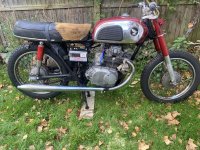
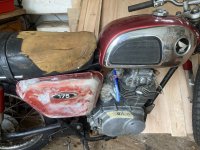
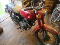
Here she is as found -
IMG_20250106_134303.jpgIMG_20250106_134250.jpg


It's missing some bits like exhausts, side panels and tank panels, but these can all be found relatively easily I hope. I've already got a few bits like the sprocket cover, one tank chrome panel and the front engine mounting plates and will be on the lookout for other bits as I go. I was very pleased that all the engine fastenings including the cylinder nuts and cover screws came off without too much trouble using the impact driver. The carb was in really good condition and still worked off the throttle grip, as did the clutch. The front brake also worked! The wiring looks ok (although it will need a good going through and I might add one of Sparckmoto's 6v reg/rec as I've used them before and they have been excellent http://www.sparckmoto.com/Products/Charging-and-Regulators). Things like the switches, lights and seat will all be serviceable with a bit of work. Mudguards are ok, too, but may need a bit of repair where the stays bolt on. The rims and spokes may be too far gone to safely use.
IMG_20250106_134310.jpg


Inside of carb - quite clean and free moving with passages and jets clear.
IMG_20250118_145941.jpg

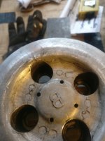
Everything was going so well that I thought I would have a look in the oil spinner and see what state that was in. In trying to get the cap off by removing the screw in the middle and then winding in an 8mm bolt I encountered my first set back, which was entirely of my own making. The bolt sheared off leaving the end stuck in the thread of the oil spinner cap! The cap was moving and I thought 'just one more turn and it'll pop out'. However the bolt I was using was obviously not very strong and it snapped!
I know I thought - I'll nip down to B+Q (DIY supply shop in UK) and get some 'easyout' type stud removers. Drilled a hole in stud (off centre naturally:unsure:) and tried to back the remains of the bolt out with a bit of heat. No movement at all and I was starting to mess up the treads of the cap. Hmm, what a pickle!

IMG_20250118_145318.jpg

I'm thinking of trying to make some kind of puller or slide hammer to fit inside the holes inside the cap and trying to pull/yank it out or I might have to try carefully sawing the spinner cap out if all else fails. Although there's a good chance I'll ruin the spinner cup as well doing this. (I see CMSNL have both in stock in case I do mess it up). Any suggestions as to the best way forward are more than welcome!
Anyway it was all going so well up to this point and I am pleasantly surprised by the condition of things once I got them apart. The engine is stuck at the moment but I've put some oil down the bores which might help release things. I imagine it's just stuck rings but I'll take the engine apart in due course to see what is going on there and maybe there will be a clue as to why it has been laid up all these years. There's only 14k on the clock and I don't think it's been on the road since the '80s so fingers crossed it's just been laid up and forgotten about.

I think the immediate plan is to get things apart then clean, repair and replace them as necessary and then try and get it back on the road. It looks a bit ratty at the moment but I think I might try and rebuild it keeping as much original as possible, including the paint and chrome as it's not really that bad and, as they say, it's only original once.
I'll post up further progress as it happens and it's nice to be back and seeing what everyone has been up to.
 
Last edited:
Sorry to hear about the delay in moving, I know what a PITA that can be to one's life. Glad to see you back, and good that you found something to work on during the interim.
 
Thanks AD. Glad to be back and looking forward to sharing my progress on the bike. It'll be ready for the summer (although I'll not be drawn as to which one!)
 
So after some thinking about the stuck spinner cap I decided to try and make some sort of slide hammer to pull it out. I made a contraption consisting of 2 allen keys and a piece of studding with an old tow hook as the weight. I welded these together. I removed any electrical bits like coils and regulator first, as I wasn't sure if I would damage them with the welding.
IMG_20250122_152403.jpg
IMG_20250122_152747.jpg
And, phew, it actually worked!
IMG_20250122_152958.jpg
So after cutting off the make-shift slide hammer I could inspect the cap and see that all my cack-handednesss with the bolt and stud extractor had cracked the area around the thread, so the cap is pretty much ruined. But at least it was out. I've managed to source a new spinner and cap from DK parts here in the UK without too much trouble.
IMG_20250122_155314.jpg
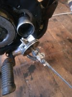
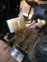
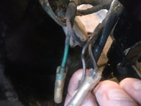
I've now taken the engine out of the bike to have a better look at it and while doing this I could see a few electrical problems that might have stopped the bike running. IMG_20250122_153013.jpg
IMG_20250122_152859.jpg
Having a look inside the spinner cup I think I could see what the problem was when trying to remove the cap with the extraction bolt method. The bolt had started to wind itself into the end of the crankshaft and had started to create a thread for itself, effectively bolting itself to the end of the crankshaft and providing no rotational movement to wind the cap out of the cup. As the engine is seized at the moment there was no rotation of the engine and crankshaft to warm me that there might be something amiss - just a lot of resistance to my turning of the bolt. I think this is something to check whenever you take the spinner cap off these engines. There isn't a lot of surface for the bolt to work against on the end of the crankshaft. I'm not sure what to do about this - perhaps debur the end of the crankshaft and make sure that there is no way for the bolt to 'catch' on the end of the crankshaft and start to wind itself in? I would imagine that if you take the cap off regularly when you change the oil and perhaps change the 'o' ring as well you shouldn't have a problem and the cap should wind out very easily - on my previous CD175 this was never a problem as it was used regularly. You could possibly make up a slide hammer out of a piece of studding to pull the cap out instead of exerting a lot of force on the extraction bolt if the cap was very stuck.
Anyway, I'm glad to have got over this problem and will have a look inside the engine top end next.
 
Last edited:
I had a bit of time yesterday and decided to have a look at the clutch and found that the pressure plate was cracked badly. It's difficult to tell from the photo but it has a slight warp on it as well so I've bought another off ebay and hope that's ok. I wonder how this cracking occurred and think it must be that the springs were not tightened down evenly and a lot of force was put on this one area of the pressure plate.
IMG_20250131_160911.jpg

IMG_20250131_161037.jpg

The clutch plates looked ok after a clean off of the fibre friction plates and a rub down of the steel ones, so they might be re-useable.
I've also filled the bores with a 50:50 mixture of acetone and ATF to see if it will free up the pistons. I'll leave it for a week then apply some heat and see if it moves. If not I'll have to grind a link off the cam chain and take the head off to see what's happening inside.
 
Hi everyone. I've not posted anything here for a little while as I sold all my motorcycles in anticipation of a house move (which has been postponed) and was also trying to reduce possessions generally. My lovely CL450 was the last to go, which I miss very much. However, having always owned a motorcycle of some sort I couldn't pass up the opportunity to rescue a 1974 CD175 which I found on ebay locally for a couple of hundred quid or so. I had a CD175 a few years ago, which was in a very bad state when I bought it, that I built up into a trials-esque type of thing with 18" wheels and TLS front brake and a few other bits. It was a very nice little bike, very easy to run and maintain and with the advantage that I could manoeuvre it out of my garden gate without too much trouble. So I was pleased to acquire this latest CD175 which is in much better condition. It has a V5 registration and it had apparently sat in a shed for at least 20 years.

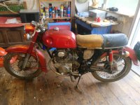
Here she is as found -
View attachment 41721View attachment 41720


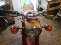
It's missing some bits like exhausts, side panels and tank panels, but these can all be found relatively easily I hope. I've already got a few bits like the sprocket cover, one tank chrome panel and the front engine mounting plates and will be on the lookout for other bits as I go. I was very pleased that all the engine fastenings including the cylinder nuts and cover screws came off without too much trouble using the impact driver. The carb was in really good condition and still worked off the throttle grip, as did the clutch. The front brake also worked! The wiring looks ok (although it will need a good going through and I might add one of Sparckmoto's 6v reg/rec as I've used them before and they have been excellent http://www.sparckmoto.com/Products/Charging-and-Regulators). Things like the switches, lights and seat will all be serviceable with a bit of work. Mudguards are ok, too, but may need a bit of repair where the stays bolt on. The rims and spokes may be too far gone to safely use.
View attachment 41727


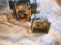
Inside of carb - quite clean and free moving with passages and jets clear.
View attachment 41722

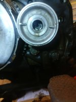
Everything was going so well that I thought I would have a look in the oil spinner and see what state that was in. In trying to get the cap off by removing the screw in the middle and then winding in an 8mm bolt I encountered my first set back, which was entirely of my own making. The bolt sheared off leaving the end stuck in the thread of the oil spinner cap! The cap was moving and I thought 'just one more turn and it'll pop out'. However the bolt I was using was obviously not very strong and it snapped!
I know I thought - I'll nip down to B+Q (DIY supply shop in UK) and get some 'easyout' type stud removers. Drilled a hole in stud (off centre naturally:unsure:) and tried to back the remains of the bolt out with a bit of heat. No movement at all and I was starting to mess up the treads of the cap. Hmm, what a pickle!
View attachment 41726

I'm thinking of trying to make some kind of puller or slide hammer to fit inside the holes inside the cap and trying to pull/yank it out or I might have to try carefully sawing the spinner cap out if all else fails. Although there's a good chance I'll ruin the spinner cup as well doing this. (I see CMSNL have both in stock in case I do mess it up). Any suggestions as to the best way forward are more than welcome!
Anyway it was all going so well up to this point and I am pleasantly surprised by the condition of things once I got them apart. The engine is stuck at the moment but I've put some oil down the bores which might help release things. I imagine it's just stuck rings but I'll take the engine apart in due course to see what is going on there and maybe there will be a clue as to why it has been laid up all these years. There's only 14k on the clock and I don't think it's been on the road since the '80s so fingers crossed it's just been laid up and forgotten about.

I think the immediate plan is to get things apart then clean, repair and replace them as necessary and then try and get it back on the road. It looks a bit ratty at the moment but I think I might try and rebuild it keeping as much original as possible, including the paint and chrome as it's not really that bad and, as they say, it's only original once.
I'll post up further progress as it happens and it's nice to be back and seeing what everyone has been up to.
Hi you seem to be well into restoring. I have a 69 CD175 sloper and I am having great difficulty trying to find a sprocket cover B, would you have any idea where I could get one. I have been to all the usual outlets with no joy. Any help would be appreciated, thanks.
Trevor
 
Hi TPG. Yes, I like the challenge of trying to get something back on the road and enjoy riding the result around. Good luck with the sloper - they are nice bikes, I believe, although I’ve not had one. Not sure about spares other than the usual sources such as eBay, etc. David Silver might have spares in addition to what’s on the website if you contact them directly. Also John Oldfield in Southampton might have some spares for a sloper 175. http://www.johnoldfield.co.uk/
Look forward to seeing your progress with the bike.
 
I’ve been a bit busy with work to do much on the bike over the last month or so but thought I’d take the engine apart to see why it is not turning, although I suspected it was perhaps just corroded piston rings from standing for so long. I also started taking things off the bike to check their condition and have been pleasantly surprised by their generally sound condition.
Starting with the cam chain. As the engine wouldn’t turn over after sitting with various concoctions of atf and acetone in the bores and being treated to sessions with the blow torch and firm pressure to the crank, etc. I decided to cut a link off the chain in order to get the head off.

IMG_20250318_134144_Original.jpeg

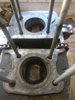
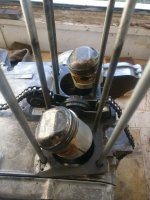
This revealed the expected crusty pistons and bores.
IMG_20250318_143924_Original.jpeg

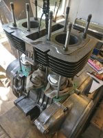
After some cleaning and gentle walloping with a mallet and piece of wood, using wooden spacers when the pistons started to move, the barrels eventually came free.

IMG_20250318_150824_Original.jpeg

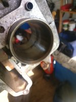
The rings were all jammed with rust and carbon and were completely stuck. I broke them all trying get them out. The pistons didn’t seem to have very much wear and they measured the standard 52mm as did the bores. I have cleaned up the barrels and I think they might be ok with a hone. Some blemish marks but nothing I can feel with my finger nail.

IMG_20250319_114818_Original.jpeg

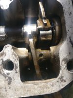
I have ordered some new pistons, rings and gudgeon pins. The rods don’t seem to have any appreciable wear and the crank spins smoothly although I will take the bottom case off and inspect a little more closely.
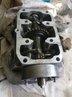
The cam shaft seems in good condition, as are the rockers. The rocker pins were difficult to remove and they were gummed up and stuck. I used the blow torch to free them up and an Allen key to pry them out and they seem to be fine. It looks like the engine and bike generally have had little wear and have just suffered from sitting for a long time.
IMG_20250319_120429_Original.jpeg

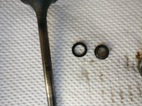
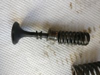
Taking the valves apart they seem to be ok and should clean up alright. I would like to get some new valve stem seals and am a little confused as to what ones will fit. I have the 2 part ones with a little washer type rubber seal and another shaped one. David Silver does not have these listed for my bike but has a similar looking top shaped one for the CB175 but without the flatter rubber seal which goes with it. Wemoto have some listed but with a generic looking picture of a one piece seal. Does anyone have any advice on which ones I should use and where I can get them?
IMG_20250406_100707_01_Original.jpeg

IMG_20250406_100840_Original.jpeg
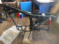
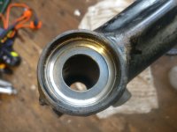
The bike is now down to the frame. The head races seem good to be used again and the frame seems straight with just a little surface rust.

IMG_20250404_074223_Original.jpeg

IMG_20250404_074230_Original.jpeg
The wiring is quite corroded with a lot of oxidisation around the connectors. I know that ‘rot’ can travel down the wires and cause problems, especially with a 6 volt system, so perhaps it might be a good challenge and exercise to make up a new loom.
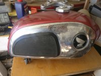
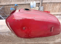
The tank has come up alright, though!

IMG_20250318_134137_Original.jpeg

I’ll inspect the bottom of the engine next and then see about putting things together again.
 
Regarding valve stem seals, I've used the David Silver single piece seals in my CD175 head (same seals as CB 175) and they are fine.

14730028013P
2
£2.75
£5.50
Valve stem oil seal
 
Had a package from David Silver today with lots of seals and bits and pieces for rebuilding the engine including seals for the camshaft, gear change and kickstarter shafts. I’ve also got the CB175 valve stem seals recommended by Richard which look identical to the CD175 ones, although there doesn’t appear to be a replacement available for the flat rubber washer type ring that goes next to the seals. Mine seem ok, although they are obviously old, so I may just put them back on.
I ordered a couple of exhaust stud/bolts as I wanted to try and change the overlong bolt on the right hand exhaust port which was obviously an ‘aftermarket’ addition and meant the exhaust collar required about an inch worth of washers before it would pull up tight.
Dome nuts are to stop me bashing myself on the studs, which I seemed to do quite a lot handling the head!

IMG_20250319_120418_Original.jpeg

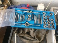
I managed to get a rather grotty bolt out of the left hand side after applying a bit of heat and replaced it with a new one but the one on the right, the extra long one, would not shift at all and I was worried about snapping it off. So I thought I’d look in my set of taps and dies and see if there was anything that would cut the thread a bit longer. I could then cut the bolt off to the right length. The thread seems to be a 6 x 1.25.

IMG_20250411_154219_Original.jpeg
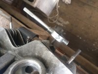
I found a right sized die and started work. The other bolt hampered the process so I had to remove the handle on every revolution to clear it but it didn’t take too long.

IMG_20250411_154111_Original.jpeg

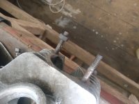
After cutting it off to the right length and giving it a file on the end it seemed to work well.

IMG_20250411_154725_Original.jpeg

Glad I didn’t persist in trying to get the thing out and quite possibly break it off.
Think I’ll have a go at putting the head back together next.
 
Nice job with the stud.

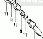
I don't remember seeing the flat rubber washer valve stem seals that you refer to, although I can see them in the CMNSL parts diagram. (#11) I just put the DS seal (#9) over the valve stem before fitting the metal 'CAP, STEM SEAL'(#10) shown in the same diagram. Seems to work OK.

1744390208934.png
 
Thanks Richard. Seems a bit odd that David Silver doesn't list the valve stem seal for the CD175 as I think it's identical to the CB175. CMSNL have both the upper and lower rubber seals listed for both the CD175 and CB175 and they are the same part numbers, although the little flat rubber seal doesn't seem to be available at the moment. I think its purpose is more to keep the other seal in place rather than as an actual oil seal - it doesn't seem to be particularly tight on the valve stem.
I need to lap in the valve seats next before I assemble the head. I've not done this before so will proceed cautiously. Any tips for this job very welcome.
 
Thanks for the advice. I think the valves and seats are in relatively good condition so hopefully not too much work will be needed to make them serviceable. Doesn’t seem to be any play between the valve stems and guides. I have some fine and coarse grinding paste.
 
The hardening on the valves is apparently quite thin, so it's easy to grind right through this with over enthusiastic lapping, then the resulting valve job doesn't last long. I was unaware of this until I came to this forum, and used to grind my valves vigorously. When I did my CD175 head recently, on advice from here I fitted new exhaust valves, rather than try to grind out some quite deep pitting. At the manufacturing stage, valve seats are simply machined using cutters, no lapping involved, and as I understand it, this is how the professionals recondition heads, new valves and machine cut seats. Serdi machine ?

And ignore any videos that show valves being rotated using an electric drill to speed up the lapping process. Although I have a nasty feeling that Allen Millyard did just that, in his Norton Nemesis rebuild series.
 
Thanks Richard. Interesting what you say about the thickness of the hardening and not going mad with the grinding. I think my valves and seats may not need much at all as they seem quite clean and smooth, so I’ll keep the lapping to an absolute minimum. I’ll try and put some decent pics up to show their condition.
I have seen videos of people using the length of rubber hose and electric drill trick but it does seem a bit brutal. Feeling things through your fingers and taking your time seems a better approach.
The bike has 14,300 miles on the clock which seems genuine and it looked like it had been reasonably well maintained until being laid up. The exhaust stud and some wiring splicing are the only obvious signs of bodgery I have found so far.
 
Thanks Richard. Interesting what you say about the thickness of the hardening and not going mad with the grinding.
Richard is correct, I believe the stellite coating for hardness is only a few thousandths of an inch.
I have seen videos of people using the length of rubber hose and electric drill trick but it does seem a bit brutal.
Yes, lapping valves with a drill is one of the more ridiculous things made even more popular by purveyors of many "help" videos by people like those guys in Houston. It's a horrible idea and only hastens the demise of a used valve.
 
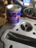
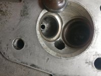
Thanks AD, I’ll be as gentle as I can with it. Here are some pics of the valves and seats and the paste I have - fine and coarse.

IMG_20250412_155555_Original.jpeg

IMG_20250412_155645_Original.jpeg
IMG_20250412_160053_Original.jpeg
 
If you're going to lap the valve look closely and measure the width of the seat when done. The contact area/band should be no more than 2mm, preferably 1mm.
Also only do a few strokes at a time, the fewer the better.
 
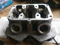
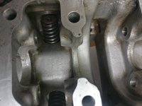
Bit of a lull in working on the bike as I've been away for a few weeks, but I managed to get the valves into the head without too much bother.
I didn't get any pictures of the process, I'm afraid. Wrestling with a dodgy spring compressor and trying to keep tabs on all the various washers and seals required a bit of concentration but I think everything went back in the right place. I had gently lapped the valve seats a bit to get rid of any obvious dirt or marking that I thought would interfere with a good seal and cleaned everything afterwards.
IMG_20250516_171640.jpg

IMG_20250516_171625.jpg

IMG_20250516_171554.jpg

Next I'll have a look at honing the barrels and fitting the barrels over the new pistons and getting the camchain and timing sorted out. I have a copy of the factory manual so will follow that.
I probably need to double check the camshaft bearing areas as I know these can be prone to oil starvation and wear. I think mine are ok but will check. Not sure if there are any measurements for how much play is allowed between the camshaft and the bearing surfaces - I couldn't see anything in the service manual?
I had to cut a link from the old cam chain to get the engine free and am assuming it would be best to get a new one and that the old one will probably be worn out. I think David Silver do them so I'll order one and have another look and make sure that I have all the gaskets and seals, etc. that I need before I start assembling things any further.
 
I'm happy to be corrected on this, but in my view the issue with the cam bearings is that they fail catastrophically if the oil supply to them is interrupted, and in these cases the damage is clearly apparent to the naked eye. Otherwise, if the bearing surfaces look smooth with no obvious marks they will almost certainly be fine. Cam journal surfaces can also get damaged by folks removing then trying to refit them without first separating the cam chain, trying to jam the journals back on against the tension of the cam chain pushing down on the camshaft.

I've compared brand new camshaft journals with used ones, trial fitted them dry to an admittedly used cam shaft, and in both cases could feel a tiny amount of play when rocking them on the cam ( as opposed to side ways end float ), no obvious difference between new and used parts.* I reckon any play is taken up by the oil film once the engine is running. You can check that oil is reaching the top of the engine by slackening the outside rear head nuts with the engine running, oil should positively gush out. From that point onwards, just a matter of checking that the oil way in the cam journal is clear. And of course in the cam itself, drillings in cam lobes feed oil onto the cam followers.

* by feel, no actual measurements taken. :geek:
 
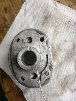
Thanks for the reply, Richard, and for your thoughts on play in the camshaft. Your point about checking the oil ways to the journals are clear had me down in the shed squirting WD40 through the various holes. One was fine but the one with the oil seal (points side I think) would not allow fluid to flow through what appears to be the oil hole. It was squirting out around the seal and not through the little hole in the spiral in the journal. Not sure if this is supposed to happen. Also, on closer inspection I could make out some scratching on the surface of the journal. So I suspect this oil way might be partially blocked. I'll get the seal out and have a closer looked to see what's going on. Here's a photo of the journal -

IMG_20250517_112645.jpg
 
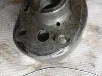
So I was just having a look at the oil ways in the head and trying to make sense of them. The one in the picture below going from the oil channel and up into the journal seemed to be slightly blocked when spraying WD40 through it but when I poked some wire through I couldn't see any dirt come out. This is the journal that looked slightly scored.

IMG_20250518_101149.jpg

I've changed to oil seal and while doing this I could see that there was a passage that went from behind the oil seal to the other side. It's the hole at the angle of the journal. Not sure what this one does as it doesn't seem to tie up with any feeds from the head. But I maybe just getting the layout of everything muddled up.

IMG_20250518_101202.jpg

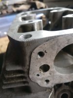
I've also blown through the oil ways from the the barrel studs at the back of the engine going through the head to the camshaft and cleaned out the passages and holes in the camshaft itself. Any idea why 2 of the holes are smaller then the other 2 - something to do with oil pressure?

IMG_20250518_101301.jpg

IMG_20250518_101310.jpg

I'll see what parts I need to complete the assembly and hope to have a go at that in the next week or so.
 
Any idea why 2 of the holes are smaller then the other 2 - something to do with oil pressure?
I'd assumed the same, smallest holes closest to where the oil enters the cam, larger ones further downstream, to even out the flow of oil to the cam followers / rockers.
 
Thanks Richard. That makes sense.
I‘ve got a couple of things on order from David Silver including some circlips for the gudgeon pins and a new cam chain, which I need to start reassembling the engine, hopefully in the next week.
 
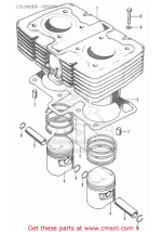
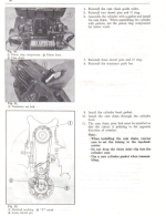
Quick question about reassembling the barrels and head. I just want to make sure I put the little rubber 'o' rings in correctly as there seems to be a discrepancy between the parts diagram and the FSM. The manual says to install an 'o' ring between the barrel and the cases and also one between the barrels and the head as far as I can tell, but the parts diagram doesn't seem to show the lower ring? Also just to confirm that they go on the rear left stud?

Screen Shot 2025-05-25 at 18.57.10.png

Screen Shot 2025-05-25 at 18.57.39.png

I'm sure this has been discussed here somewhere but I can't find a clear answer and various videos on youtube seem to gloss over the issue.
Any advice gratefully received as I want to get things in the right order!
 
I've never read the top end assembly section of the 175 FSM until today, and I'm surprised that it's not directly referenced or even a picture of the correct o-ring arrangement. The oil flow diagram seems to show both outer rear studs take oil to the top end, but it's been decades since I've had a 175 engine apart so I'll defer to @Richard Pitman for the proper answer.
 
The two rear outer studs take the oil up to the head, and the 'O' rings fit between the cylinder head and the top of the cylinder, as seen here in this pic of my SL175 engine rebuild,

sz29Qsr.jpg
 
Fantastic. Thanks, Richard. Makes sense now. I thought what the manual was suggesting seemed a bit odd.
 
Well, it's been a while since I posted on progress with the bike but I have found some time push things forward a little.
Thanks to help from the forum members I've managed to put the engine together and fit it into the frame, get the wheels and hubs serviced and fitted with new tyres, clean the carb, fit a battery and empty the forks of fluid and check them over.

IMG_20250530_140228.jpg

IMG_20250530_140207.jpg

I've assembled most of the running gear and am going to have a go at the wiring next. The original loom doesn't look too bad so I think I may try with that first and if (when) it doesn't work I'll deal with faults as I find them. I'm sure it would be prudent to replace the whole loom (and perhaps make one myself as an interesting exercise?), especially with a 6v system. I may get a new modern regulator/rectifier unit, although I don't think the UK CD175 came with a regulator, as the old rectifier is probably a bit past it.

IMG_0074.JPG

Managed to find some second-hand silencers on ebay, which were made in Thailand and are not too far from the original style and can be made to fit.

IMG_0076.JPG

David Silver has replicas of the original ones but they are very expensive and I can't justify the expense on a 'just get it going' project (must do something about the seat though!).
So, electrics next and see if it will spark and fire!
 
Last edited:
Might be worth doing the 12volt conversion if you are getting a new reg/rec and building a new loom. A 12 volt battery fits in the stock battery holder if you just make up a new retaining strap ( and is probably easier than finding a new 6 volt battery ), CD175 stator is the same as the CB 12 volt part. I'm using same battery as an SL175, 5ah from memory.

1765914431841.jpeg
 
Thanks Richard - that's a good idea. I think I read about how to do the conversion some time in the past and it didn't sound too difficult.
I've just found this reference by Simo to a 12v conversion on his CD175 on the old site in 2012 -

"I converted my cd175 to 12v
you need a 12v stator ( cb/cl 175 or 200 , 80watt or 97watt respectively ) all 12v bulbs ,a 12v coil and condenser ,12v starter solenoid, 12v flasher unit, 12v rec/reg and a 12v battery and fuse
the only bits you keep stock are the harness , starter and points"

Does this sound about right? Of course the starter parts wouldn't relevant on a UK CD175 and you say the stator shouldn't need changing. Would I need to adapt the wiring in the existing stator in any way?
Also perhaps the existing horn might not work on 12v?
 
I'd guess maybe a 12v coil but the condenser should work as is (they can generally handle much higher voltage. Starter and solenoid would also work but if used too much would eventually fail, flasher unit I'd expect would need to be changed and of course the proper 12v rec/reg unit. But, the stator puts out ac voltage and should provide close to the same level of voltage that will be converted to dc so I'd suspect it would be fine as is. And the horn would work for a while too but would certainly scream louder for a bit... :giggle:
 
Rob Fryatt covers the 6v to 12v conversion further down his thread about fitting a starter motor to his CD175. He confirmed that the stator output was OK, and kept the 6v coil by fitting a ballast resistor and relay. 6v horn worked, just louder !

 
Thanks for the information everyone. It would be a good time to be doing the conversion while I'm tackling the wiring. It sounds like a good idea and many people seem to have done 12v conversions on their old British motorcycles in the past to improve reliability. There must have been a good reason to switch from 6v to 12v by vehicle manufacturers.
I'll see about collecting the parts that I need. Good to know the stator I have will do the job and the other parts are pretty cheap and readily available.
I'll let you know how it goes.
 
Hello everyone and apologies for the lack of progress and postings. Time seems to have flown by and I just haven't been able to find a moment to do anything on the bike. However I have recently bought another CD175 which was for sale locally as a source of parts and possibly to use as the basis for a future project.
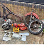
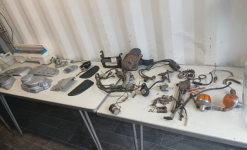
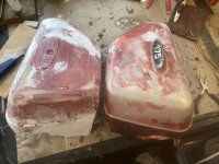
I had been looking for some side panels which as you know are very rare these days, as they get brittle and easily broken. Spares generally for these bikes seem to be getting more pricey, but this has meant that there are some quite good reproductions available now as it is worth while making them. But they are expensive. Anyway the bike I bought (which was in pieces) had some battered panels and an engine that turned over so I thought it worth the couple of hundred quid I paid.

IMG_1009.PNG
IMG_1010.PNGIMG_1011.PNG

It's incomplete - missing a swinging arm, seat and exhausts - but has lots of useful bits. I've applied for a registration document as the previous owner didn't have one but it's still on the DVLA database and hasn't been nicked as far as I can tell so fingers crossed that I might be able to get it registered in my name, which will be a bonus.

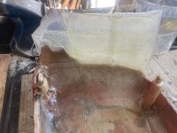
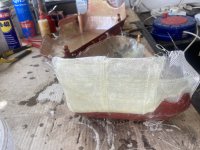
The side panels were a bit worse than I thought but I decided to have a go at reclaiming them anyway.
IMG_1019.JPG
IMG_1018.JPG

I used epoxy resin and fibreglass to stick the bits back together and then used some filler to start to even the surfaces out.

IMG_1053.JPG

This is as far as I've got at the moment but I think I can get them to look fairly presentable with a bit of elbow grease. One little problem, though is that these panels are off a later CD175 and the lower fixing tab seems to be in a slightly different location to my earlier bike. Not sure why they would have changed this location. I'll have to investigate this further and think about a solution.

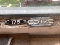
I've also got a mixed pair of badges as well. I need two of the oval ones. If anyone needs a squared one or wants to do a swap, let me know.

IMG_1054.JPG

That's all for the moment - getting the side panels in some sort of decent shape and primered is my next task.

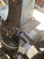
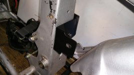
Update! I've just looked more closely at the bottom location mounts for the side panels and can see that they are attached to a 'tray' which bolts to the frame with some captive nuts. I can see that this tray appears to be in the wrong place as there are 2 holes higher up to which the 'tray' could be bolted that should align the panel and grommet correctly. Not sure why this piece should be in the wrong location but it's how the bike came to me. Interesting!

IMG_1140.JPG

IMG_1141.JPG


Success!

IMG_1142.JPG
 
Last edited:
Well worth 200 quid !

That tool tray had me scratching my head for while when I was assembling my CL175 hybrid ( CD engine ), which has the large CD right hand cover and the little CL cover on the left (exhaust) side. It mounts in the same area as the CB 175 tool box, which is probably what the alternative set of mounting holes are for. Both bikes ( CD and CB ) use the same frame of course.

I have both tool tray and box sitting in my shed, I made up a bracket in the end to take the bottom mounts of the two differing side panels. I assume that on the CD, the tools are just kept in the plastic bag, bungied onto the open tray.
 
Thanks Richard - yes, I thought it was worth getting. The engine looks to be in good condition, spins over freely and has been stored with the plugs in and the carb. on so has not had too much moisture in it. The last engine I bought some years ago was about £150 for a working engine but they seem to be double that for a broken one now.
Interesting that you had a similar issue with the tool tray on your hybrid bike and glad you found a way round it. It had me stumped for a bit and I was imagining all sorts of solutions including cutting up the side panels and making new attachment pegs!
I'm still waiting on the DVLA to see if they will give me a registration for the new bike and if they do I think I might make another bitsa like my first CD175 'trials' bike. Not sure when I should follow them up as it's been 5 weeks now with no word but they can be a bit slow to process things.
 
Only just seen this thread. When I had my CD, I was debating about converting to 12 volts. But in the end, I just changed the indicators to LED. The originals really were dim as buggery.
Here’s a link to that thread in case you go that way. Richard helped me there as you’ll see.
 
DVLA - I've registered 3 bikes with them, and two registrations were back virtually by return of post. I sent my documents recorded delivery, cost around 7 quid, from memory. The last one was the SL175 bitsa, there had been a confusion over the NOVA number ( they had two SL175 frames on NOVA numbers, got them back to front ) sorted out easily in a phone call.

Bracket that I made:
1784400350631.jpeg
Trial fit on spare frame

1784400388715.jpeg
 
Thanks for the link WJ, it looks like any upgrade to the original electrics and lighting would be very worthwhile.
Thanks also for the pic of the bracket, Richard, that's a really nice job, just like a factory fitting.
I'll contact the DVLA and see if there's any news on my registration. It was a V62 form to apply for a change of keeper and lost reg. docs.
 
Back
Top Bottom