A meticulous restoration of a CB72 '67 (and a SS50Z K3)

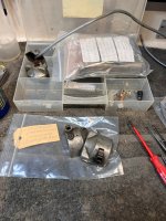
Like mentioned earlier, although I'll switch to E-ignition, I also want a complete functional / original points ignition as a backup. So, the next step in the wiring harness preparation is mounting of the condensers. The CB72 has the condensers mounted underneath the right coil bracket, a much better and accessible place then the awkward choice of Honda engineers placing the condensers on top of the engine, like the C77 dream.

But before I could mount the condensers, I had to locate the, yellow plated, 5mm JIS screws. Luckily I worked 7 years for a Japanese company, so getting the right JIS hardware wasn't so difficult.

Afbeelding van WhatsApp op 2025-10-31 om 09.02.08_9e9dd578_cut.jpg

Locating the little screws took longer then mounting the condensers and putting the bracket back to the frame.

Afbeelding van WhatsApp op 2025-10-31 om 09.02.08_2fa88723.jpg

The wires of the condensers are cut, so I have to add new bullet connectors. I think I have to order a bunch of bullet connectors anyway, because my stash dried up lately (CD50H, CB400F, SS50Z K3).

I was a little fed-up with the electrics (not my hobby), so I went to some mechanical work, in this case mounting the rear fork.

While disassemble the rear fork for painting preparation, I managed to push out the rear fork bushings in one piece, just like the collars. After measurement, of bushings and collars, I decided to replace only 2 bushings (out of four), and only one collar. I did use the new parts on the right side (chain side) and the best 2 out of four bushes and the best collar out of the two on the left side. All bushings and collars where within spec (no radial play) but the surface of one of the collars was a little scored.

Luckily I didn't had to buy them, I had both items them in stock.

Afbeelding van WhatsApp op 2025-10-31 om 09.02.08_a46e8385.jpg

Afbeelding van WhatsApp op 2025-10-31 om 09.02.08_e4108ebd.jpg

Afbeelding van WhatsApp op 2025-10-31 om 09.02.09_f3c3ce8e.jpg

Two old bushes and the scored collar are going back into my stock for the next CB72, both are within spec, but I like to use them on the left side (not the chain side).

I don't know what the prices are today, but the total repair was only 6 euro's for the bushings, and 4 euro for the collar.

Afbeelding van WhatsApp op 2025-10-31 om 09.02.08_e9c2fd7b.jpg

Nice and tidy, I pressed the bushes in with a vice, not ideal, but it works. In the close-up one can see that the paint job is kind of rough, that's because the paint is sprayed directly over the bare metal, no fillers, no epoxy under-layer. It's a industrial paint, specially designed for this kind of work. It's not going to be a show bike anyway, so I'm happy with it (and the price was good too). Like mentioned earlier, I only painted the parts that aren't directly in sight, so fuel-tank, headlight ears, headlight shell, front fork covers will stay as they are, being original paint with a little patina.

Afbeelding van WhatsApp op 2025-10-31 om 09.02.09_8ee6bdb1.jpg

I also found NOS rubbers (mounted on the insight of the fork bearings), and a nicely, plated nut and shaft completing the picture.

Afbeelding van WhatsApp op 2025-10-31 om 09.02.09_e985a025.jpg

Not much to tell, but just a nice picture. I really like the setup with the aluminium parts.

Afbeelding van WhatsApp op 2025-10-31 om 09.02.09_a3dd7c92.jpg

And the other side as well.

Afbeelding van WhatsApp op 2025-10-31 om 09.02.09_ab7eabee.jpg

After assembly I greased the bearings via the grease nipple's on both sides of the rear fork axle until the grease was visible on the outside of both bearings. The movement up and down of the rear fork is nice and smooth, absolutely no radial play, and certainly no axial play as well.

I know that many people replace those bushings by bronze ones, but I decided to use the "plastic" bushings from Honda. Regular maintenance (once a year using the little grease gun) is the key.

Afbeelding van WhatsApp op 2025-10-31 om 09.02.09_94bcda60.jpg

The grease nipple's Honda uses on there early bikes are sometimes hard to reach with modern grease guns, especially the one at the left side. I use this special, old handy small grease gun I got with the CB400F. I'm grateful that the PO of the CB400F thought about these little things. This grease gun is leak-free (you can close it off), and is small enough to stash it in the bike's tool tray.

As you can see, the grease gun is heavily used, the black coating on the outside is almost worn down to bare metal.

Next job is the wiring to the tail light, head light and winkers, adding a battery and battery clamp so I can find a place for all the extra electronics (E-ignition, headlight relay's and the reg/ rec unit).
 
Oops, I made a mistake. Not a big one, but since the information in this thread and forum goes worldwide, and hopefully stays accessible for a long, long time, I have to correct it.

In post 376 I posted a picture of the clamp / bracket that holds the winker relays, but is mounted the wrong way.

Here a picture how it should be mounted:

Afbeelding van WhatsApp op 2025-10-31 om 14.38.33_2c3138cf.jpg

The winker relay should be placed behind the frame tube, not before. In the pictures of my CB72'61 and this one, the bracket was mounted wrong. In the japanese CB72 partsmanual it clearly shows the relay on the backside of the frametube, and that makes sense.

However, room is limited, so I had to add the fuel tank stay rubber plus mount first to determine my working area. The rubber is also replaced with one out of my spares. The clamp underneath the rubber is painted, the same way as the frame.

Afbeelding van WhatsApp op 2025-10-31 om 14.38.33_8b8dc7d5.jpg

From that point I tried to move around the winker relay clamp / bracket with the winker relay itself, and found a high position the best.

Afbeelding van WhatsApp op 2025-10-31 om 14.38.33_604e82f1.jpg

Now there is still space for the battery, and it doesn't touch the fueltank stay.

Afbeelding van WhatsApp op 2025-10-31 om 14.38.33_70d662e2.jpg

I'm glad I dove into that little Japanese parts manual, since there aren't much pictures on the world wide web or manuals.

btw, I mentioned that one collar was scored, and the reason to me was lack of maintenance, well, pictures of the scoring proves that I was correct.

Afbeelding van WhatsApp op 2025-10-31 om 14.38.33_164eae40.jpg

This area turns in a "plastic" bush, and is only scored on a small area (around 60 degrees of the full circle). With a decent fresh amount of grease once in while, pushing the old grease with particles out, and checking the rear-chain tension, this would never have happened. Regular maintenance saves lot's of dollar's or euro's.
 
Last edited:
One step up, two steps down, and then 3 steps up, so just one step further today. First of all, I forgot to mount the side stand bracket, and since the bracket has to be placed behind the aluminium part, I had to loosen the rear fork nut again. I also replaced the engine mounting bolt (MF10*45 mm) with the special, longer bolt (MF10*55 mm). Luckily I had a few in my stash, because these bolts are hard to find. The threads of these engine bolts is different then ordinary M10 thread (M stands for metrical, F stands for Fine).

Since people wonder how to mount the side-stand bracket (it is very unclear in the parts manual), I made a clear picture of it. The bracket is hold in place by the lower left engine bolt (the MF10*55mm) and a special, 10 mm longer then standard, main stand bolt. I know I have tow of them re-plated, but I couldn’t find them in the box I expected them. No hurry, I will hunt them down, and make sure I keep them in eye-sight . The side stand bracket isn't plated jet, I forgot about it. But a second bracket is ready for plating, and will be in the next batch of parts to plate. This bracket is painted, I did that years ago, but it's ugly and should be zinc plated.

Afbeelding van WhatsApp op 2025-11-01 om 20.41.54_2493a8fa.jpg

The aluminium brackets are prone to crack, so mounting them without any stress is important, and today, when mounting the side-stand bracket, I didn't feel confident about the right bracket. The brackets are resting onto two surfaces, and both surfaces should be perfectly aligned with the surface of the aluminium bracket. On those two points, a lot of force is applied by two bolts, one is the rear fork axle and the other one a bolt in the frame.

Afbeelding van WhatsApp op 2025-11-01 om 20.41.54_0a2218c5.jpg

Any height difference will result in too much stress, and thus a risk on cracking. On the right side I had to add a 1 mm shim between the rear fork shaft and the bracket to make sure that the bracket was just touching the lower frame point.

Afbeelding van WhatsApp op 2025-11-01 om 20.41.54_523725f6.jpg

The left side is good, so finished that part. Next is adding the front fork and main stand.
 
Last edited:
This is the special side-stand bolt for the left side. It's 10 mm longer and is impossible to find. Only used on the '61 model and the police versions.

sidestand bolt CB72'61.jpg
 
This is the special side-stand bolt for the left side. It's 10 mm longer and is impossible to find. Only used on the '61 model and the police versions.
Yikes. That kind of price gouging would have me looking at a replaceable sleeve bushing, unless I had one handy, of course.
 
Yikes. That kind of price gouging would have me looking at a replaceable sleeve bushing, unless I had one handy, of course.

The blue CB72 '61 came with one, a few years later, I acquired, per accident, another one. In the past there were some guys on Ebay, that sold these bikes (early CB450's, CB72's and 305's) in parts. The left-overs (bolts, nuts, rings, springs and small brackets) were mostly sold for a very low price, (nobody was really interested), and in a time that shipment meant shipment, the weight didn't matter. And yes, almost 25% to 50% of all those parts were molested, but 75% to 50% was very useable. These nuts, bolts, rings, springs and brackets that could be saved are now re-worked, threads are re-cut, and most of it is zinc-plated. All those parts are categorised and added to inventory, stored in a wall of sorting boxes.
 
Last edited:
The wiring diagram of the CB72 is not so complex, but needs an appropriate breakdown, especially the combination of ignition switch, headlight switch and switchgear makes things a little mysterious. There are no switch gear braeakdown schemes drawn or pictures, neither in the diagrams nor in the shop manual. To try to understand what is switched by which contact, a breakdown of the switchgears is necessary.

Headlight switch (the switches for the whole range over the years are the same, from '61 to '67):

- the switch has 5 wires
- the switch has three positions

The switch sequence is best displayed in a picture (the first column is the name of the contact, the second column is the wire colour, the other three columns are the knob positions) :

headlight switch CB72.jpg

Interesting to see is that the second position doesn't "switch" or connect anything, the first and third positions are connecting as per scheme above.
 
Seems strange that position 2 is nothing (remove key?).
No, this is the switch in the head housing, it's not an ignition switch, just a knob with three positions. I measured 3 out of 6 I have, everyone of them exactly the same switching behaviour, position 2 is the centre position.
 
Last edited:
No, this is the switch in the head housing, it's not an ignition switch, just a knob with three positions. I measured 3 out of 6 I have, everyone of them exactly the same switching behaviour. But it get's even more mysterious, and I found an error in the official Honda shop manual.
Oh, that's better. It would allow starting without lights on for better power.
I do like the C/CA function for starter only to prime the motor prior to ignition, when it is cold.

An actual error and not just a translation glitch?
 
The ignition switch (key-switch), located at the rear, and has 3 positions as well.

- the key-switch has 5 wires
- the key switch has three positions

The key switch sequence is best displayed in a picture (the first column is the name of the contact, the second column is the wire colour, the other three columns are the knob positions) :

key-switch.jpg
 
Oh, that's better. It would allow starting without lights on for better power.
I do like the C/CA function for starter only to prime the motor prior to ignition, when it is cold.

An actual error and not just a translation glitch?

Not a glitch, a mistake in the drawing of the wiring diagram.

Check the original wiring diagram in de shop manual, and look / compare with the pictures below, do you see it ?

Afbeelding van WhatsApp op 2025-11-02 om 18.31.05_d3c9ea79.jpg

Switch contact disc

Afbeelding van WhatsApp op 2025-11-02 om 18.31.05_80448aa5.jpg


Afbeelding van WhatsApp op 2025-11-02 om 18.31.06_8056e052.jpg

Old grease, cleaned it, and put new grease in before assembly.

Afbeelding van WhatsApp op 2025-11-02 om 18.31.06_4d7e0218.jpg

The switch actuator, this part turns with the key.

Afbeelding van WhatsApp op 2025-11-02 om 18.31.06_2f43beb1.jpg

A few balls , springs and contact plates, all in good health.

Afbeelding van WhatsApp op 2025-11-02 om 18.31.06_c0c22a2c.jpg

Before assembly , I cleaned the surfaces of the contacts, by using sandpaper 2000 on a flat surface. After cleaning, greasing with dielectric grease to keep the contacts in good shape.

Afbeelding van WhatsApp op 2025-11-02 om 22.18.30_c0846aea.jpg
 
1762120003524.png

I don't understand the inclusion of CH in the key switch, the rectifier output is still directly connected to the battery.
 
Last edited:
It must have to do with the rectifier, battery wiring colors and that red/white switch connection.

Hint : Look closely (!) to the Sachse wiring diagram in post 359, that came from the original FSM together with what you mentioned above.......
 
Last edited:
Afbeelding van WhatsApp op 2025-11-01 om 21.58.18_0de83011.jpg

Afbeelding van WhatsApp op 2025-11-01 om 21.58.18_0de83011_cut out.jpg

Harness A, (dotted wires), the connection from the battery, non-fused is connected to the GR wire, which connects to HL, but should be connected internally to the W/R wire instead. The way it is connected in the drawing, the battery will not be charged, there is no connection between the rectifier and the battery.
 
This is the same erroneous drawing in my English FSM. Several illogical aspects involved.
Honda should have sent Jensen an official corporate rice bowl and plane ticket to Japan.

It does seem that Honda was still looking for a way to standardize the electrics for all country's and continents with minimum effort. For example, there are two types of headlight switches, (268 and 270), with a different switch behavior, but exactly the same housing. The only difference is the lower contact / connection plate, so most parts are the same, thus cheaper to produce. A key switch with the red/white connection, connected to nothing, maybe already prepared for an upgrade, who knows. Then the connections between the two switches, where Honda uses a black / red wire to give power to the headlight switch, and call it IG (ignition), although, the only function is to bring power to the headlight.
 
Looking at the functionality of the key-switch of the Honda dream, and a discussion with @ballbearian about the advantages of having a prime function of the engine, and trying to think what I want, and how it should work from my perception, I made a wish-list.

A wish-list is what it is, not sure if it's within the possibility's of the switch sequences / contacts. It's an R&D approach, not yet hampered or hindered by real world limitations or by any detailed knowledge of the realistic possibilities and im-possibilities.

(wished) function of the main key switch:

pos 1: everything off
pos 2: power to all users, except ignition and head light
pos 3: power to all users including ignition and power to headlight switch

(wished) function of the headlight switch (the headlight switch is only functional when the key-switch is in position 3):

pos 2: neutral position, thus everything works, but no lights on
pos 1: power to all users, as pos 3 and parking light and taillight on (daylight running lights) but no headlight
pos 3: power to all users, including headlight and taillight

The big win would be the function of position 2 of the key-switch. Everything works, except ignition (no power to the coils), when switched on, and a possibility to prime the engine with the starter motor. Maybe a handy function is to have a taillight and parking light on, not sure about that yet. I would call it a test and prime position. Position 2 and 3 of the key-switch can be interchanged as well, depending on the possibility's.

Since I never park my bike in a rural area, the function of switching on parking light and taillight on while key being removed isn't necessary for me.
 
Last edited:
A little bit of puzzling turned the wishlist's into a suggested realistic possibility:

Suggested function of the main key switch:

- pos 1: everything off

- pos 2: power to all users including ignition and power to headlight switch
BA-Battery
IG-Ignition only
HL Battery (externally wired to BA)
TL all users except ignition and connected to headlight switch

- pos 3: power to all users, except ignition
BA Battery
TL all users except ignition, and connected to headlight switch

Suggested function of the headlight switch (the headlight switch is only functional when the key-switch is in position 3):

- pos 2: neutral position, power to all users thus everything works, but no lights on

- pos 1: power to all users, as pos 3 and parking light and taillight on
IG power from key-switch
ML parking light / rear light

- pos 3: power to all users, including headlight and taillight
HL parking light / rear light
DY power from key switch (externally wired from IG)
SE headlight power to handlebar light switch

The big win is the function of position 3 of the key-switch. Everything works, except ignition (no power to the coils), when switched on, and a possibility to prime the engine with the starter motor. No taillight and parking light on. I would call it a test and prime position. The key can be removed from position 3, so still the choice to switch taillight and parking light on, or even the headlight on when you want.
 
Last edited:
Afbeelding van WhatsApp op 2025-11-03 om 22.32.22_0c0668f3.jpg

According to the Honda parts manual the CB72 has two head light switches, 35150-268-010 and 35150-270-000 number, however, in my stash I also found a NOS light switch in a bag, with the number 35150-268-000, but that number doesn't exist in the parts manuals I have. But if I feed the part number to the CMSNL website, it seems to exist, but no picture. There is also a 35150-268-810 number according to the CMSNL website, and that one has only 4 wires instead of 5.

35150-270-000 is for general export and, according to the CMS website, it has 4 wires, pink, yellow, green and black.
35150-268-810 is for the USA, and according to the CMS website, it has also 4 wires, same colours as above.

The CMS-website doesn't show any 5 wire switches, and that's strange, because all the switches I have are switches with 5 wires, the extra wire is brown.

Afbeelding van WhatsApp op 2025-11-03 om 22.32.21_153aeb14.jpg

Afbeelding van WhatsApp op 2025-11-03 om 22.32.21_f0266f1e.jpg

Afbeelding van WhatsApp op 2025-11-03 om 22.32.21_fa5c65dc.jpg

Afbeelding van WhatsApp op 2025-11-03 om 22.32.21_38ec8203.jpg

All the above used switches are in good working order. I assume the NOS ones I have are good too (not tested).

Before completing the wiring harness, I have to fix the handle bar switches first, because the switches on this bike were a mess.

Afbeelding van WhatsApp op 2025-11-04 om 22.05.34_463b5708.jpg

Taking the switches apart is the first step, then cleaning the parts, soldering new wires in the right colours, and put them back together.

Afbeelding van WhatsApp op 2025-11-04 om 22.05.34_d4b239d6.jpg

Afbeelding van WhatsApp op 2025-11-04 om 22.05.34_8f7ea643.jpg

Luckily, the contacts are in good shape, that good.

Tonight I also added some nice goodies to the bike, a NOS starter relays, and a NOS key-switch with keys and a steering stem lock with the same key's (Honda sold these as a set).

Afbeelding van WhatsApp op 2025-11-04 om 22.05.34_1812b8a9.jpg

Afbeelding van WhatsApp op 2025-11-04 om 22.05.34_dd4634b4.jpg

The used key-switches will be restored, if I can get my hands on the key's.

Afbeelding van WhatsApp op 2025-11-04 om 22.37.39_6f692cac.jpg

A nice view. The used starter relays will be restored as well, ready for installation in the future or on another CB72 (after this one, there are 2 more, a 1961 and an in-between model (1961 / 1962).
 
Both the early Benly and Dream had it but the 65 Benly and Dream did not.

Not really needed as both models had run without lights positions of key switch.
 
If the pink (DY) and the yellow (SE) were connected via the switches but the dimmer did nothing (middle notch), then would extra charging take place?
 
The wiring harness is designed, drawings are made, switch and relay logic is tested (software simulation), so now I'll get my hands dirty, starting with the handlebar switches, I cleaned my workshop, cleaned the desk, and prepared for cutting wires, soldering, sleeving, crimping, etc.

What is better then start the day with a long walk before riding the bike to work. It was cold this morning, but sunny.

Afbeelding van WhatsApp op 2025-11-06 om 22.46.15_3492a9fd.jpg

The colours are nice, some leaves are almost shining. The sun (behind me) was just reaching the trees on the other side of this field.

Afbeelding van WhatsApp op 2025-11-06 om 22.46.16_71b63519.jpg

Afbeelding van WhatsApp op 2025-11-06 om 22.46.16_4ed98ce9.jpg

I started with the winker switch. The switch was a mess, wrong wire colours, wrong sleeve, nasty soldering work. The good thing was that there wasn't much wear, and all parts were there. I just needed to clean the contacts with 2000 sandpaper, and use some dielectric grease on the contacts.

Afbeelding van WhatsApp op 2025-11-06 om 22.46.16_1f71e29c.jpg

I don't want to loose any small part, so boxing up per switch area.

Afbeelding van WhatsApp op 2025-11-06 om 22.46.16_619844a4.jpg

Much better, and the right colours. I have a box full of wires that I took from wire harness that were too far gone, or far to modern for the bikes I have.

Afbeelding van WhatsApp op 2025-11-06 om 22.46.16_70d149d6.jpg

Everything in place.

Afbeelding van WhatsApp op 2025-11-06 om 22.46.16_ed3085e7.jpg

Everything done, except for the sleeve.

Afbeelding van WhatsApp op 2025-11-06 om 22.46.17_6b5125e5.jpg

And sleeving the wires with flexible PVC tube. Unfortunately it's grey, not silver, but the shipping costs for the correct silver sleeves are just a little too steep for me. The Honda wires have thick isolation, much more then modern wires, the wires just fitted the sleeve, no room for an extra wire. Since the Hi/Lo switch is only switching relay's, I'll use modern wires (1.0 mm2), same as Honda, but thinner isolation. Makes the wires better to bend, that's a win.
 
I was annoyed that there is a mistake in original the wiring diagram from the FSM (no connection between rectifier and battery) so I corrected it for future consultations (habit of an engineer). For the later Honda's there are also switching diagrams added, but not for the CB72 / 77, so I added the ones I made, but altered those in the Honda style. As far as I know, this is one of the few, or maybe the only correct wiring diagram with switching diagrams in the world (at least I never came across one) @ancientdad, you may add this one to the forum library. I'm also working on a correct wiring diagram with winkers, that I will add later.

correct bedradingsschema Honda CB72 met schakellogica.jpg
 
Last edited:
Will do, but I'm afraid the changes are not completely clear to me visually. Some color added to depict the differences would be helpful.

The original diagram is also without colour, the difference is a wrong connection in the dotted line from battery to the wire W/R instead of Green, the connection itself is a dot (to make it clear were this wire is connected to). I added a piece of dotted wire in the exact same style, colour and width as Honda uses. In post 418, I displayed the error (hence the red circle).
 
The upper pic of the handlebar H/off/L is an older type with an in between off position.

I dove in this matter as promised (accidental, while refurbishing the HI / LOW switchgear), and I think I've solved the puzzle. Looking very close to the HI / LOW switch, I saw that someone carefully filled away the letters R/L, and stamped the letters G/ D (stands for the Dutch words Grootlicht / Dimlicht).

Afbeelding van WhatsApp op 2025-11-09 om 09.51.41_2943fca9.jpg

Afbeelding van WhatsApp op 2025-11-09 om 09.51.41_edf95813.jpg

This was probably done in a time that people didn't value these bikes anymore, and made changes to parts to modernise the bike. The reason people did these modifications are simple / logic. From factory, on the very early bikes, the HI / LOW switch gear is placed on the left side, and due to the fact that winkers weren't mandatory, but optional, Honda added a winker switch on the right side. On later bikes, for example the CB450 K1, and from that bike almost all bikes, the winker switch was placed on the right side, which makes more sense.

One of the PO's of this bike was probably used to have the winker switch on the left side, and decided that it was a good idea to change the the right side.

Well, making a long story short, this is probably why the wiring of the handle bar switch gear is such a mess.

The contacts of this switchgear was worn a little but too much, so I had to re-surface and flatten the contact area's. I filled a 30 degree slope angle to the left and right contacts to have a smooth transition between the positions.

Afbeelding van WhatsApp op 2025-11-09 om 09.51.41_ffc296f4.jpg

Since I have all tools in place, a clean workshop and an automated workflow and experience, I decided to restore / rewire all handle bar switchgears from the CB450 K0's, the CB72 / 77's and dream, that will keep me from the streets for a while :rolleyes:.
 
Last edited:
The 3 ball bearing detents would make sense for a winker switch but un-needed with the off position on the nacelle light switch.
Perhaps the PO just detested the English designations. Good for me, I got a small lesson in Dutch.
 
That's a good idea to give the slider contact a little ramp to slide up and onto the contacts.
Thanks, on my CB450 K0 I had a Hi/Low switch that was very difficult to slide up and down. I took it apart, and saw that the sharp edges on the contacts were the issue, I filled them in a slope, and everything went smooth.
 
The next CB72 in the project row is a '61 / '62 bike, a bike that has some parts from the '61 and some parts from a '61, it is a in-between bike. At that time Honda just did things different. My 1961,5 bike has also winkers, but, in this case it was a special kit.

Afbeelding van WhatsApp op 2025-11-09 om 16.45.45_58f9f7ef.jpg

This part fits onto a (special) right handlebar lever bracket. When I got the CB72, I thought that someone did a funny job to add winkers to the bike, so I took it off and bagged it as, well, non-Honda electrical parts.

But a few years later I visited a well known Honda Guru, and writer of the book "pictorial history of Japanse motorcycles", **** van de Heuvel. I was yoking around about the funny winker switch, but he went quit, and took me upstairs to a CB92, and showed me this:

strange and early winker switch CB72.jpg

I was astonished to see the same winker switch, and the special bracket, and **** asured me that it was 100% original Honda, and sold as a kit for the CB92 and CB72 in 1960.

Another winker switch, for the CB72, but now the original left side winker switch. The red wire colour of the original wires is period correct, and I leave it that colour.

Afbeelding van WhatsApp op 2025-11-09 om 16.45.45_558ed951.jpg

And while I was at it, I also added a CB450 K0 switch combination to the workload for the coming days.

Afbeelding van WhatsApp op 2025-11-09 om 16.45.45_4016f12f.jpg

I bought this 2nd hand, and paid around 30 euro for the whole set.

Afbeelding van WhatsApp op 2025-11-09 om 16.45.46_8a02a5ca.jpg

And another winker switch, in a bad state, no wires, but all the internal parts are there. In this case it's a right hand side winker switch, the same one that has been altered into a Hi / Low switch by a PO.
 

Attachments

  • Afbeelding van WhatsApp op 2025-11-09 om 16.45.46_8a02a5ca.jpg
    Afbeelding van WhatsApp op 2025-11-09 om 16.45.46_8a02a5ca.jpg
    296.5 KB · Views: 2
The next CB72 in the project row is a '61 / '62 bike, a bike that has some parts from the '61 and some parts from a '61, it is a in-between bike. At that time Honda just did things different. My 1961,5 bike has also winkers, but, in this case it was a special kit.

View attachment 52206

This part fits onto a (special) right handlebar lever bracket. When I got the CB72, I thought that someone did a funny job to add winkers to the bike, so I took it off and bagged it as, well, non-Honda electrical parts.

But a few years later I visited a well known Honda Guru, and writer of the book "pictorial history of Japanse motorcycles", **** van de Heuvel. I was yoking around about the funny winker switch, but he went quit, and took me upstairs to a CB92, and showed me this:

View attachment 52207

I was astonished to see the same winker switch, and the special bracket, and **** asured me that it was 100% original Honda, and sold as a kit for the CB92 and CB72 in 1960.

Another winker switch, for the CB72, but now the original left side winker switch. The red wire colour of the original wires is period correct, and I leave it that colour.

View attachment 52208

And while I was at it, I also added a CB450 K0 switch combination to the workload for the coming days.

View attachment 52209

I bought this 2nd hand, and paid around 30 euro for the whole set.

View attachment 52211

And another winker switch, in a bad state, no wires, but all the internal parts are there. In this case it's a right hand side winker switch, the same one that has been altered into a Hi / Low switch by a PO.
I see the the name has disappeared, let’s call the guy Cornelis, but here in the Netherlands Kok, but then with ck at the end is a normal name
 
After a little bit of trail and error, I implemented the functionality as suggested in post 351 plus more. The diagram also works more or less for the CB450's. All switches, except a part of the headlight bucket switch (parking light, tail-light and speedo backlight), only switch a low power relay. I use automotive Normally Open and one or two changeover micro relays (sealed), and switched on, they only consume 80-100 mA each. I also chose to build-in a trickle charge connector, and only works when everything but the battery is disconnected.

The relays for the headlight (3) are located in the headlight itself, the other two are placed near the battery. The diagram is a functional diagram, and shows only the main power distribution and switching logic. The only colour you will find is the positive of the battery, no coloured wires here. The thick lines carry the main current, the thin lines are control current. Each group has it's own fuse for safety reasons.

- The starter motor can run without ignition (keys-switch position III) for priming the engine oil and fuel.
- The taillight is connected to the parking light, just as in the original diagram.
- When charging the battery with a trickle charger, the voltage regulator must be disconnected, this is now possible with key-switch in position I.
- The voltage regulator is only connected when the ignition is switched on, with the key-switch in position II.

And last but not least, the original wiring can be used, only the control current need an extra wire through the wire harness, but maybe I can use the pink wire, or the yellow wire, these wires won't be used any-more.


functional wiring diagram Honda CB72.jpg

Tonight I did build up the part for the headlight, and that worked surprisingly well.
 
Last edited:
Made a small change to protect ignition for high peaks from the generator in to the voltage regulator when the engine is shut off with the key switch while the generator is still generating power. I also connected it directly to the battery, no fuse inbetween any-more.

aangepast schema Honda CB72.jpg
 
Hmm, can't find a non board micro relay with 2 changeover contacts, thus replaced with two relays, one NO, and one with changeover contacts so back to the drawing board.

final wiring diagram CB72.jpg
 
Yes, it's complex for a bike of the 60's, and, over-engineered as well. But it's logic, and above all, save. The current trough the switches is low, less contact burning. These relays are cheap and reliable automotive parts, standard material, commodity stuff, less then 3 euro's a piece, so increased the value of the CB72 with 18 euro's ;)

Enough work done on the wiring diagrams for CB72, now back to the reality, and implement everything in the real world bike.

I also worked out the other function groups in drawings, one drawing for each function group, but not worth displaying.
 
The robust OEM hardware with your upgrades would probably blow the minds of the original designers/engineers.
Interesting to see what sort of switch hardware you find for the K stand and F brake.
 
The robust OEM hardware with your upgrades would probably blow the minds of the original designers/engineers.
Interesting to see what sort of switch hardware you find for the K stand and F brake.
Well I don't think so, but at that time, engineers had a different mind-set and less possibility’s to work with. The later Honda bikes have very complicated wiring diagrams and wire harnesses, with lot's of relays (fuel cut-off, engine cut-off, etc).

I have located a front brake cable with switch, which fit's the CB72 (second-best solution), still looking for a robust solution for the side-stand. I could add a micro switch into the handlebar bracket, but the brackets for this CB72 with winkers are very special, so, not an option to alter these.
 
Today, my LED H4 bulbs came in, The brand is Osram, and the package looked nice.

Afbeelding van WhatsApp op 2025-11-13 om 22.12.32_7be282ab.jpg

I went for a 2700K colour temperature, which is very close / the same to the original headlight incandescence bulb, and that's why these LED lamps called vintage. It is a little bit of a gamble, because the bulbs have a build-in van, making the bulbs large.

Afbeelding van WhatsApp op 2025-11-13 om 22.12.32_aa7f7c69.jpg

I have a few H4 headlight units, and because this is for the CB72, I started with the headlight shell of the CB72 to see it it would fit in.

Afbeelding van WhatsApp op 2025-11-13 om 22.12.32_7e3444ae.jpg

Well, it did, and I have plenty of room left.

Afbeelding van WhatsApp op 2025-11-13 om 22.12.32_1aa5bfaf.jpg

I started with a German made Hella headlight unit.

Afbeelding van WhatsApp op 2025-11-13 om 22.12.31_f4aeb370.jpg

The inside glass is a little dusty, I will clean that later.

Afbeelding van WhatsApp op 2025-11-13 om 22.12.32_cb2dde16.jpg

I tested the headlight outside, and it seems good enough, much. much better the the original one. These Osram LED lamps are road-legal for most bikes (not mine), but the light image is good.

It's a set of two, the other one is for the CB400F, which I will build in tomorrow.
 
Since the C77 dream headlight output isn’t that good in the original set-up, tried to fit the LED lamps onto the dream headlight. The lamp doesn’t fit, so it has made to fit. Did the measurements, and next week I will print a testpart. If that works, I’ll print it in peek.

f61ceb46-20c6-4aae-89e4-3ea0e5c47632.jpeg
e0ff52bd-6184-4725-a4c4-5072bcfa9975.jpeg

One is aftermarket, the other one is Honda, both have the same fitment.
 
Back
Top Bottom