
Snicks
Well-known Member
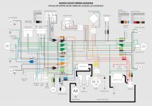
I wanted to share a wiring diagram I made for this specific bike US version 1975 (but was actually made in 1974). I made it to teach myself the electrics of a bike and I thought it might be helpful for others. The year of the bike is important because, according to 66Sprint, the little green tail ground from the solenoid to the battery negative is an arrangement used until this specific solenoid's inventory was used up before switching to a different solenoid.
I'm uploading an image of the overall diagram as well as a PDF of the colors separated into separate images. I did this so it's easier to focus how each component is connected through the wires' colors. A high resolution of the overall diagram is also in the PDF.
CB200T Wiring Diagram PDF
(I can't seem to adjust settings in this forum format.) - Edit: fixed it for you - ancientdad
The wiring diagram is an update from the one found specifically in the owner's manual—it is more detailed than the one found in the shop manual or the Clymer's manual.
The components are updated to the following with some notes:
If there are any mistakes found, please let me know and I'll update the diagram.
Hope this helps!
I'm uploading an image of the overall diagram as well as a PDF of the colors separated into separate images. I did this so it's easier to focus how each component is connected through the wires' colors. A high resolution of the overall diagram is also in the PDF.
CB200T Wiring Diagram PDF
(I can't seem to adjust settings in this forum format.) - Edit: fixed it for you - ancientdad
The wiring diagram is an update from the one found specifically in the owner's manual—it is more detailed than the one found in the shop manual or the Clymer's manual.
The components are updated to the following with some notes:
- regulator/rectifier combo unit (the Yellow and White Yellow from the stator is merged into one Yellow wire. Wiring for old regulator edited.)
- 2 prong flasher relay for LED lights (the Black of the relay is the load side according to this specific model so it plugs into the Grey wire. not the harness Black as you might think!)
- LED turn signal indicator light in tachometer (a non-polarization bulb was used so a diode is not needed to prevent back flow over the turn signal circuits. Avoids flashing-lights-all-the-time syndrome.
- LED lights for all bulbs except for headlight (headlight was updated to a H4 bulb using the stock lens. Hack was made following TStephenGaunt's retrofitting post from the old forum)
- Points and Condenser taken out and replaced with Charlie's Place electric ignition.
If there are any mistakes found, please let me know and I'll update the diagram.
Hope this helps!
Attachments
Last edited by a moderator:


